
High-speed micro-coaxial connector assembly and male connector

A connector assembly, ultra-fine coaxial technology, which is applied in the direction of protective grounding/shielding device of connecting parts, parts of connecting device, connection, etc. Instability and other problems, to achieve the effect of improving transmission stability and anti-interference ability, improving shielding and grounding ability, and saving internal space

Active Publication Date: 2022-04-01
CHINA AVIATION OPTICAL-ELECTRICAL TECH CO LTD
View PDF9 Cites 0 Cited by
  • Summary
  • Abstract
  • Description
  • Claims
  • Application Information

AI Technical Summary

Problems solved by technology

[0002] With the development of high-speed connectors towards miniaturization, high density, and high speed, low cost and high reliability are also crucial. Distributed inside the connector, high-speed performance cannot be realized; in addition, the shielding structure plays a very important role in the field of high-speed connectors, and the design of the shielding structure directly affects the high-speed performance of the connector. The shielding of existing coaxial cables mainly relies on The shielding layer inside the cable is connected to the metal shell by means of a conductor structure. The conductor structure is generally a wire or shrapnel. This method can only achieve independent grounding of a single coaxial cable, while the shielding grounding of multiple coaxial cables , the layout of multiple conductor structures will inevitably occupy a large internal space of the connector, and the shielding performance is not stable, and the shielding effect is average. Therefore, the coaxial cable connectors for high-density deployment in the prior art have not yet been perfected. shielding structure for common ground shielding

Method used


Image

  • High-speed micro-coaxial connector assembly and male connector
  • High-speed micro-coaxial connector assembly and male connector
  • High-speed micro-coaxial connector assembly and male connector

Examples


Embodiment Construction

[0042] Further detailed description will be made below in conjunction with the accompanying drawings and preferred embodiments.

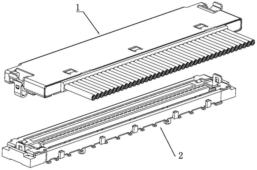
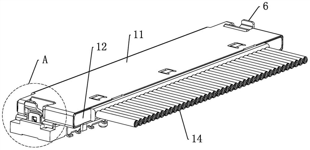
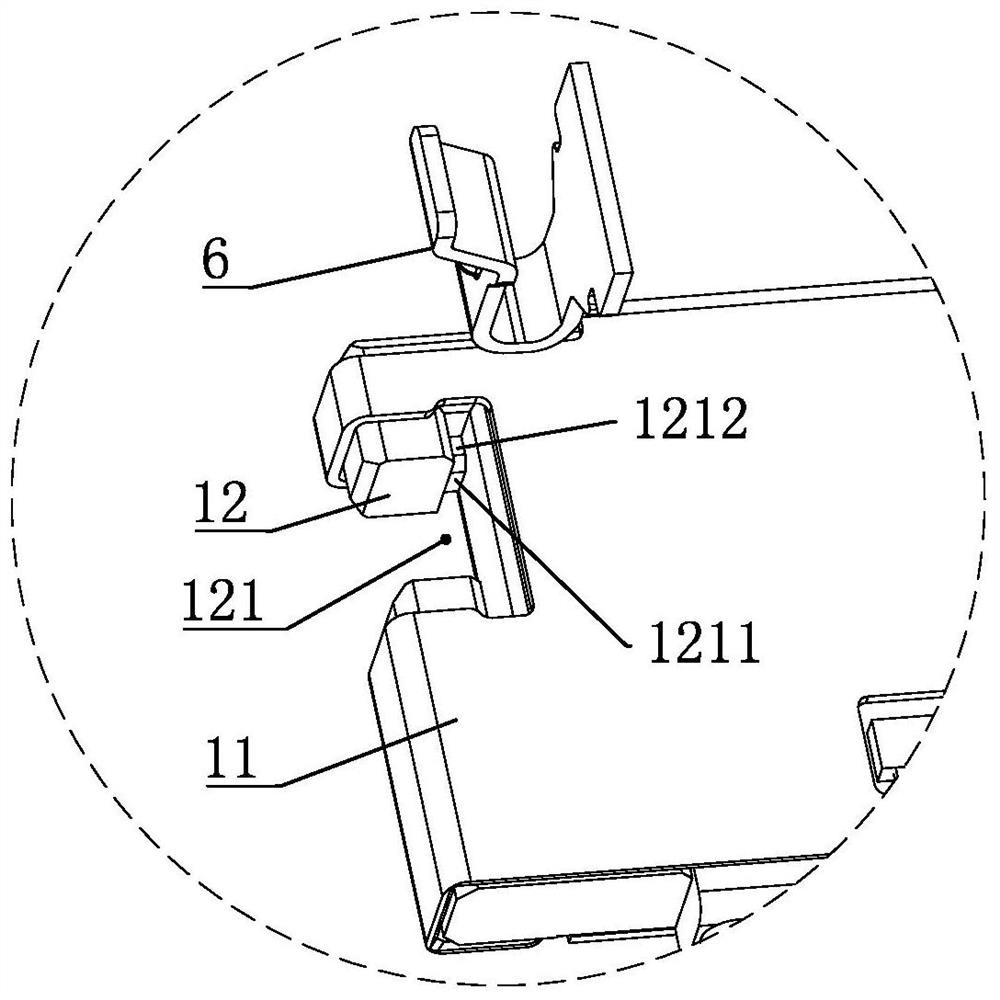
[0043] Examples of high-speed micro-coaxial connector assemblies, such as Figure 1 to Figure 19 , including a mating male connector 1 and a female connector 2, the male connector 1 includes a male shielding shell 11, a male insulator 12 disposed in the male shielding shell 11, arranged in a row on The male terminal 13 in the male insulator 12 and the coaxial cable 14 connected to the male terminal 13 in one-to-one correspondence; the diameter of the coaxial cable is 0.30mm, but the present invention is not limited to this, the coaxial cable The wire diameter of the cable can be adaptively adjusted according to actual needs. The female end connector 2 includes a female end insulator 21, a female end shielding shell 22, and a female end terminal 23 arranged in a row in the female end insulator. The female end shielding shell 22 is installed on the f...


PUM


Abstract

The present invention relates to a high-speed ultra-thin coaxial connector assembly and a male-end connector. The high-speed ultra-thin coaxial connector assembly includes a male-end connector and a female-end connector, and the male-end connector includes a male-end shielding shell, a male-end insulator, Male terminal and coaxial cable, the male terminal is installed in a row in the male insulator, one end of the male terminal is a terminal, the other end has a plug-in terminal, the wire core in the coaxial cable is welded to the male terminal, The shielding layer in all coaxial cables is welded between the upper and lower conductive strips, the upper conductive strip is in contact with the shielding shell of the male end, and the lower conductive strip is in contact with the shielding sheet; the female end connector includes a female end insulator, a female end shielding shell And the female terminals arranged in a row in the female terminal insulator, one end of the female terminal is the welding end, and the other end is the contact end; in the mated state, the plug-in end contacts the contact end, and the shielding plate and the female terminal shielding shell conduction. The invention realizes full-envelopment shielding in the mating area of ​​the male and female terminals, improves the stability of signal transmission, and facilitates the realization of high-speed performance.

Description

technical field [0001] The invention belongs to the technical field of connectors, in particular to a high-speed ultra-thin coaxial connector assembly and a male end connector. Background technique [0002] With the development of high-speed connectors towards miniaturization, high density, and high speed, low cost and high reliability are also crucial. Distributed inside the connector, high-speed performance cannot be realized; in addition, the shielding structure plays a very important role in the field of high-speed connectors, and the design of the shielding structure directly affects the high-speed performance of the connector. The shielding of existing coaxial cables mainly relies on The shielding layer inside the cable is connected to the metal shell by means of a conductor structure. The conductor structure is generally a wire or shrapnel. This method can only achieve independent grounding of a single coaxial cable, while the shielding grounding of multiple coaxial c...

Claims


Application Information

Patent Timeline
Patent Type & Authority Patents(China)
IPC IPC(8): H01R13/648H01R13/652H01R13/46H01R13/40H01R24/38H01R13/516
CPCH01R13/648H01R13/652H01R13/46H01R13/40H01R24/38H01R13/516
Inventor 李栋刘成荫阎瑞兵
Owner CHINA AVIATION OPTICAL-ELECTRICAL TECH CO LTD
Learn More