High-speed connector assembly and its latch

A high-speed connector and connector technology, which is applied to the parts, connections, and protective grounding/shielding devices of connecting devices, etc., can solve the problems of large rotation track of the retaining ring, difficult operation, and inability to achieve high-speed performance. Improve high-speed performance, facilitate miniaturization, and facilitate high-density deployment

Active Publication Date: 2022-04-01
CHINA AVIATION OPTICAL-ELECTRICAL TECH CO LTD
View PDF7 Cites 0 Cited by
  • Summary
  • Abstract
  • Description
  • Claims
  • Application Information

AI Technical Summary

Problems solved by technology

[0002] With the development of high-speed connectors toward miniaturization, high density, and high speed, low cost and high reliability are also crucial. Distributed inside the connector, making high-speed performance impossible
Combined with the application scenarios of miniaturized high-speed connectors, the setting environment is narrow and difficult to operate. However, the current locking structure for the mating and locking of the connectors at both ends of the male and female uses a buckle or thread locking structure, and the rotation track of the buckle is large. , which is not conducive to use in a narrow space; thread locking is cumbersome to operate, which is not conducive to quick insertion and removal

Method used


Image

  • High-speed connector assembly and its latch
  • High-speed connector assembly and its latch
  • High-speed connector assembly and its latch

Examples


Embodiment Construction

[0035] Further detailed description will be made below in conjunction with the accompanying drawings and preferred embodiments.

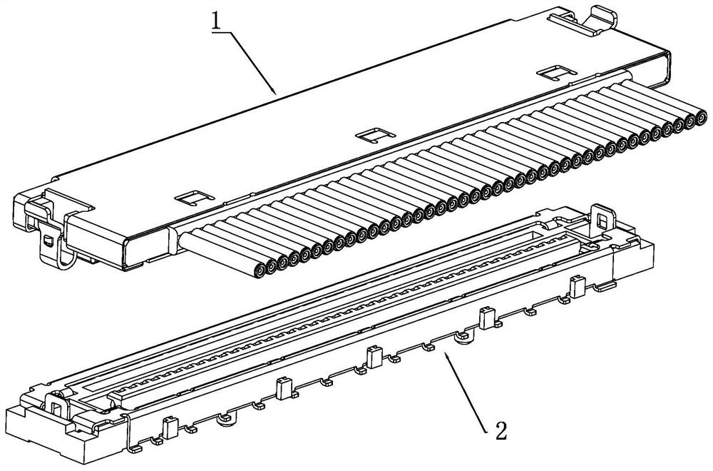
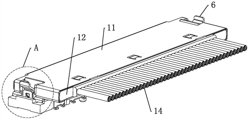
[0036] Examples of high-speed micro-coaxial connector assemblies, such as Figure 1 to Figure 19 , including a mating male connector 1 and a female connector 2, the male connector 1 includes a male shielding shell 11, a male insulator 12 disposed in the male shielding shell 11, arranged in a row on The male terminal 13 in the male insulator 12 and the coaxial cable 14 connected to the male terminal 13 in one-to-one correspondence; the diameter of the coaxial cable is 0.30mm, but the present invention is not limited to this, the coaxial cable The wire diameter of the cable can be adaptively adjusted according to actual needs. The female end connector 2 includes a female end insulator 21, a female end shielding shell 22, and a female end terminal 23 arranged in a row in the female end insulator. The female end shielding shell 22 is installed on the f...


PUM


Abstract

The present invention relates to a high-speed connector assembly and its latch. The high-speed connector assembly includes a male-end connector and a female-end connector. The male-end connector includes a male-end insulator and male-end terminals arranged in rows in the male-end insulator. There are locks on both sides of the end insulator; the female end connector includes the female end insulator and the female end terminals arranged in rows in the female end insulator, the female end insulator is provided with the female end shielding shell, and the two sides of the female end shielding shell There is a lock groove corresponding to the lock buckle, and the lock buckle is snap-connected with the lock groove to realize the mating and locking of the male and female connectors; after mating and locking, the female terminal and the male terminal are in contact with each other. In the present invention, the male-end connector is locked with the female-end connector through a lock, which is convenient and fast, and adapts to the narrow connector installation environment, which is beneficial to the miniaturization of the connector size and facilitates high-density deployment of the connector; the male / female terminal They are arranged in a row in the connectors at the corresponding ends, ensuring the high-speed performance of the connectors.

Description

technical field [0001] The invention belongs to the technical field of connectors, in particular to a high-speed connector assembly and a lock. Background technique [0002] With the development of high-speed connectors towards miniaturization, high density, and high speed, low cost and high reliability are also crucial. Distributed inside the connector, making high-speed performance impossible. Combined with the application scenarios of miniaturized high-speed connectors, the setting environment is narrow and difficult to operate. However, the current locking structure for the mating and locking of male and female connectors adopts a buckle or thread locking structure, and the rotation track of the buckle is large. , It is not conducive to use in a narrow space; the thread locking is cumbersome to operate, which is not conducive to quick insertion and removal. Contents of the invention [0003] In order to solve the problems of the prior art, the present invention propo...

Claims


Application Information

Patent Timeline
Patent Type & Authority Patents(China)
IPC IPC(8): H01R13/639H01R13/648H01R13/40H01R13/516H01R24/00
CPCH01R13/639H01R13/648H01R13/40H01R13/516H01R24/00
Inventor 李栋刘成荫阎瑞兵
Owner CHINA AVIATION OPTICAL-ELECTRICAL TECH CO LTD
Why Eureka
Try Eureka