Battery voltage indication and protection circuit

A battery voltage and protection circuit technology, applied in emergency protection circuit devices, measuring current/voltage, electrical components, etc., can solve the problems of high cost, many circuit devices, complex circuits, etc., and achieve convenient control, low cost, and simple structure Effect

Inactive Publication Date: 2014-10-15
OCEANKING DONGGUAN LIGHTING TECH +2
View PDF6 Cites 7 Cited by
  • Summary
  • Abstract
  • Description
  • Claims
  • Application Information

AI Technical Summary

Problems solved by technology

[0003] The above-mentioned circuit devices are many, the circuit is more complicated, and the cost is higher

Method used


Image

  • Battery voltage indication and protection circuit

Examples


Embodiment Construction

[0014] The following will clearly and completely describe the technical solutions in the embodiments of the present invention with reference to the accompanying drawings in the embodiments of the present invention. Obviously, the described embodiments are only some, not all, embodiments of the present invention. Based on the embodiments of the present invention, all other embodiments obtained by persons of ordinary skill in the art without creative efforts fall within the protection scope of the present invention.

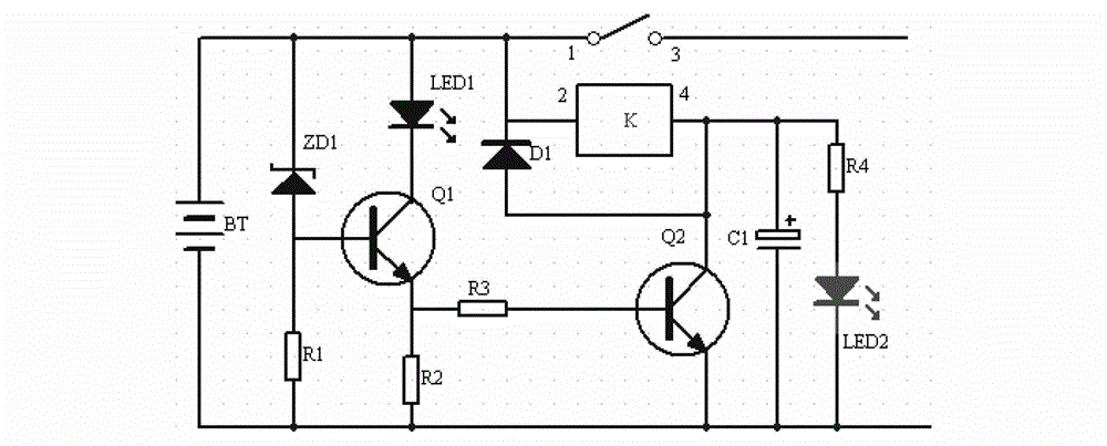
[0015] Please refer to figure 1 , a battery voltage indication and protection circuit, including transistors Q1, Q2, voltage regulator tube ZD1, diode D1, relay K, battery pack BT, display lights LED1, LED2, resistors R1, R2, R3, R4; Q1 bases respectively Connect with one end of R1 and the positive pole of ZD1; connect the collector of Q1 with the negative pole of LED1; connect the emitter of Q1 with one end of R2 and one end of R3 respectively; connect the base of...


PUM


Abstract

An embodiment of the invention discloses a battery voltage indication and protection circuit. The battery voltage indication and protection circuit includes triodes Q1 and Q2, a voltage-regulator tube ZD1, a diode D2, a relay K, a battery pack BT, display lamps LED1 and LED2, and resistors R1, R2, R3 and R4; a base electrode of Q1 is connected with one end of R1 and a positive electrode of ZD1; a collector electrode of Q1 is connected with a negative electrode of LED1; an emitting electrode of Q1 is connected with one end of R2 and one end of R3; a base electrode of Q2 is connected with the other end of R3; a collector electrode of Q2 is connected with a positive electrode of D1, a fourth pin of K and one end of R4; an emitting electrode of Q2 is connected with a negative electrode of BT, the other end of R1, the other end of R2, a negative electrode of LED2 and one end of a load light source drive circuit; a negative electrode of ZD1 is connected with a positive electrode of BT, a positive electrode of LED1, a negative electrode of D1, a first pin of K and a second pin of K, and a third pin of K is connected with the other end of the load light source drive circuit; and a positive electrode of LED2 is connected with the other end of R4. The battery voltage indication and protection circuit in the embodiment of the invention has the advantages of simple structure, convenient control and low cost.

Description

technical field [0001] The invention relates to the field of lighting driving battery protection, in particular to a battery voltage indication and protection circuit. Background technique [0002] Reference document A battery discharge protection circuit capable of self-locking (Chinese Patent Application No. 201010147371.4), an AC-regulated DC stabilized power supply of the present invention, consisting of a reference circuit, an undervoltage detection circuit, a charging detection circuit, and a self-locking protection circuit Circuit, protection output circuit consists of five parts. The undervoltage detection circuit detects the low voltage of the battery and outputs the battery undervoltage signal, triggers the protection self-locking circuit to form a self-locking control protection output circuit to shut down the output, when the battery is charged, the charging detection circuit detects the output charging signal and triggers the protection self-locking circuit to u...

Claims


Application Information

Patent Timeline
Patent Type & Authority Applications(China)
IPC IPC(8): H02H7/18G01R19/165
Inventor 周明杰杨俊昌
Owner OCEANKING DONGGUAN LIGHTING TECH
Why Eureka
Try Eureka