Test tube placement rack with lifting structure for medical equipment

A technology of lifting structure and medical equipment, applied in the direction of test tube holder/clamp, laboratory equipment, etc., can solve the problems of inconvenient, troublesome, inability to tilt the test tube rack, etc., achieve convenient and convenient operation, ensure not easy damage, and ensure stable center of gravity sexual effect

Inactive Publication Date: 2021-01-15
杭州华慧医药科技有限公司
View PDF0 Cites 0 Cited by
  • Summary
  • Abstract
  • Description
  • Claims
  • Application Information

AI Technical Summary

Problems solved by technology

[0004] The purpose of the present invention is to provide a test tube rack with a lifting structure for medical equipment, to solve the problem that the test tube rack needs two hands when moving, which is troublesome, and some test tube racks cannot be tilted, which is inconvenient The problem

Method used


Image

  • Test tube placement rack with lifting structure for medical equipment
  • Test tube placement rack with lifting structure for medical equipment
  • Test tube placement rack with lifting structure for medical equipment

Examples


Embodiment Construction

[0020] The following will clearly and completely describe the technical solutions in the embodiments of the present invention with reference to the accompanying drawings in the embodiments of the present invention. Obviously, the described embodiments are only some, not all, embodiments of the present invention. Based on the embodiments of the present invention, all other embodiments obtained by persons of ordinary skill in the art without making creative efforts belong to the protection scope of the present invention.

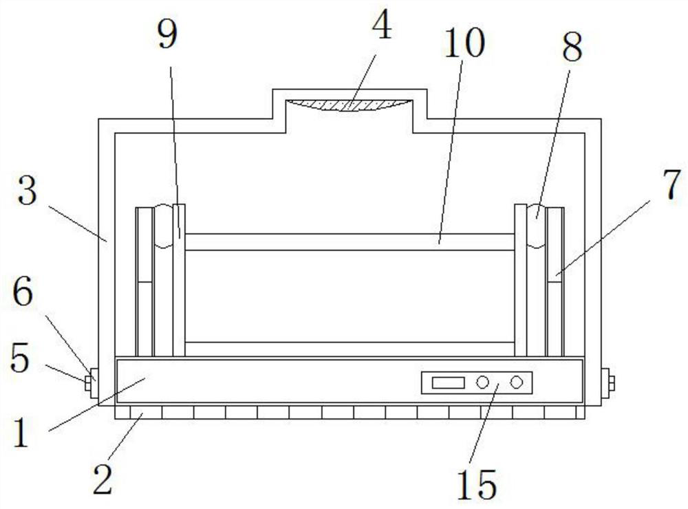
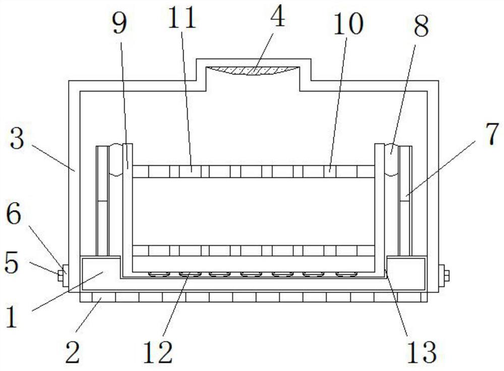
[0021] see Figure 1-3 , the present invention provides a technical solution: a test tube placement rack with a lifting structure for medical equipment, including a base 1, a flexible pad 2, an armrest frame 3, a sponge layer 4, bolts 5, nuts 6, lifting rods 7, The rotating shaft 8, the placement frame 9, the support frame 10, the placement slot 11, the protection slot 12, the limit slot 13, the limit buckle 14 and the console 15, the bottom of the base 1 is f...


PUM


Abstract

The invention discloses a test tube placement rack with a lifting structure for medical equipment, which comprises a base and a placement rack body. A console is arranged at the middle end of the right side of the base, armrest frames are installed on the two sides of the base, sponge layers are arranged in the middles of the top ends of the armrest frames, and bolts are arranged on the two sidesof the bottoms of the armrest frames; nuts are attached to the middle ends of the bolts, telescopic rods are fixed to the two sides of the upper portion of the top of the base, and rotating shafts areconnected to the side edges of the telescopic rods. The test tube placement rack with the lifting structure for the medical equipment is provided with the base and the flexible pad, the base and theflexible pad are fixedly connected, so that the working strength is easier, meanwhile, the damage degree of test tubes is reduced, the connecting strength is high, the stability of the test tubes on the support frame is guaranteed, and the base is vertical along the flexible pad; and the flexible pad has pressure resistance, so that the base can be well stressed, the stability of the gravity center of the whole equipment can be effectively ensured, and the contact surface is not easy to damage.

Description

technical field [0001] The invention relates to the technical field of a test tube placement rack for medical equipment, in particular to a test tube placement rack with a lift structure for medical equipment. Background technique [0002] Today's test tube rack is the most basic experimental instrument for placing (sometimes the test tube can also be placed on the test tube rack to observe the phenomenon of a certain experiment) and drying the test tube. A corresponding number of small wooden columns and small holes are attached to the test tube rack. If there is a small hole, the test tube can be placed upright for use or in order to continue to observe the progress of the reaction. If there is a column, the clean test tube can be turned upside down for drying. [0003] The test tube racks on the market are in use. The test tube racks used are generally similar in structure, but at the same time, some deficiencies and areas that need to be improved will be found. The tes...

Claims


Application Information

Patent Timeline
Patent Type & Authority Applications(China)
IPC IPC(8): B01L9/06
CPCB01L9/06B01L2200/02
Inventor 柳皓
Owner 杭州华慧医药科技有限公司
Why Eureka
Try Eureka