Semiconductor device

A semiconductor and device technology, applied in the field of semiconductor devices, can solve the problem of reducing the quality factor of inductance devices

Active Publication Date: 2014-10-15
SEMICON MFG INT (SHANGHAI) CORP
View PDF5 Cites 2 Cited by
  • Summary
  • Abstract
  • Description
  • Claims
  • Application Information

AI Technical Summary

Problems solved by technology

However, the shielding structure of the prior art will reduce the quality factor Q of the inductance device

Method used


Image

  • Semiconductor device
  • Semiconductor device
  • Semiconductor device

Examples


no. 1 example

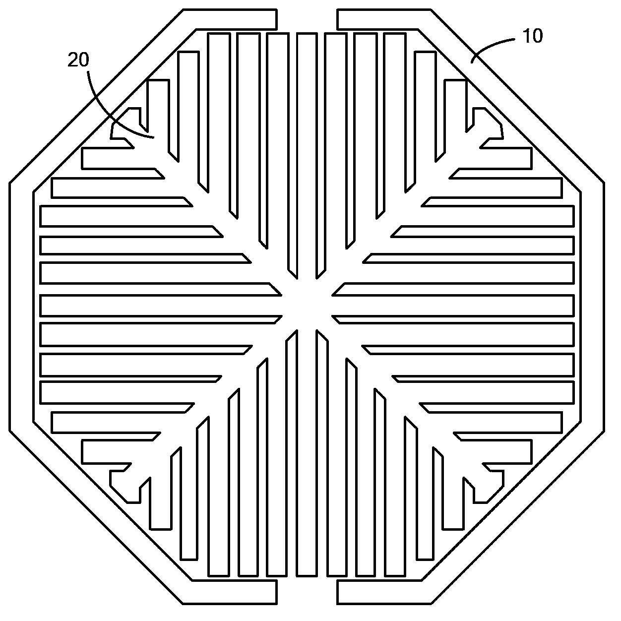
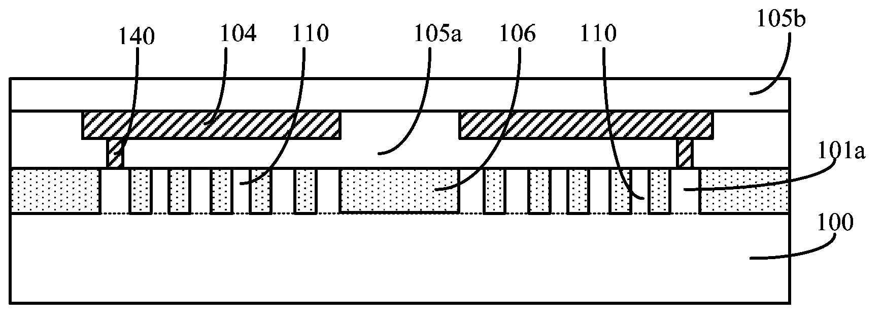
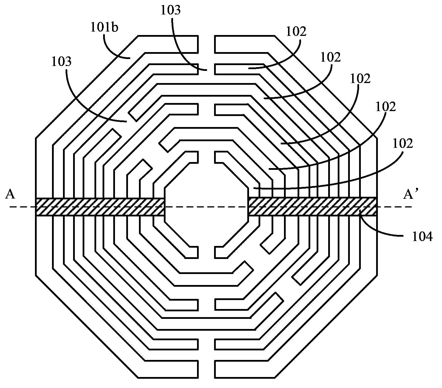
[0037] Please refer to figure 2 and image 3 , image 3 It is a top view structure diagram of the grounding metal ring, the conductive ring and the conductive wire in this embodiment, figure 2 yes image 3 A schematic cross-sectional structure along the AA' direction, including: a semiconductor substrate 100; a grounding ring on the surface of the semiconductor substrate 100; a grounding shielding structure on the surface of the semiconductor substrate 100, the grounding ring surrounds the grounding shielding structure, the The ground shielding structure includes several concentric conductive rings 102 (such as image 3 shown), and the conductive wires 104 passing through the plurality of conductive rings 102 along the radial direction of the conductive ring 102, and the conductive wires 104 are electrically connected to the grounding ring, and the plurality of conductive rings 102 each have a plurality of openings 103 ( Such as image 3 shown), and the openings 103 of ...

no. 2 example

[0064] The difference between the second embodiment and the first embodiment is that it further includes: a polysilicon ring located between the active region ring and the metal ring, the position and shape of the polysilicon ring correspond to the metal ring, and the The polysilicon ring is electrically isolated from the metal ring and the active area ring by a dielectric layer. It will be described below in conjunction with the accompanying drawings.

[0065] Please refer to Figure 6 to Figure 9 , Figure 6 is a schematic cross-sectional structure diagram of the semiconductor device of the second embodiment, Figure 7 yes Figure 6 A top view of the active area ring shown, Figure 8 yes Figure 6 A top view of the polysilicon ring shown, Figure 9 yes Figure 6 The top view of the metal ring 230 and the conductive wire 204 shown includes: a semiconductor substrate 200; a ground ring located on the surface of the semiconductor substrate 200; a ground shield structure ...


PUM

PropertyMeasurementUnit
Widthaaaaaaaaaa

Abstract

Provided is a semiconductor device which comprises a semiconductor substrate; a grounding ring which is arranged on the surface of the semiconductor substrate; a grounding shielding structure which is arranged on the surface of the semiconductor substrate; a dielectric layer which is arranged on the surface of the semiconductor substrate, the grounding ring and the grounding shielding structure; and a semiconductor device body which is arranged on the surface of the dielectric layer. The grounding ring encloses the grounding shielding structure which comprises multiple concentric conductive rings, and a conductive wire which penetrates through the multiple conductive rings along a radial direction of the conductive rings. The conductive wire and the grounding ring are electrically connected. The multiple conductive rings are provided with multiple openings, and the openings of the adjacent conductive rings are arranged in a staggered way. The dielectric layer encloses the grounding ring and the grounding shielding structure. According to the semiconductor device, shielding capacity can be enhanced, substrate loss can be reduced and performance of the semiconductor device can be enhanced.

Description

technical field [0001] The invention relates to the technical field of semiconductor manufacturing, in particular to a semiconductor device. Background technique [0002] In existing integrated circuits, such as CMOS radio frequency integrated circuits (RFIC), inductor is an important electrical device, and its performance parameters directly affect the performance of integrated circuits. In the prior art, most of the inductors in integrated circuits use planar inductors, such as planar spiral inductors; the planar spiral inductors are formed by winding metal wires on the surface of a substrate or a dielectric layer; compared with traditional wire wound inductors, planar inductors The device has the advantages of low cost, easy integration, low noise and low power consumption, and more importantly, it is compatible with today's integrated circuit technology. [0003] For inductive devices, there is a quality factor Q to measure their performance. The quality factor Q is th...

Claims


Application Information

Patent Timeline
IPC IPC(8): H01L23/552H01L23/58H01L23/64
Inventor 程仁豪王西宁刘凌
Owner SEMICON MFG INT (SHANGHAI) CORP
Why Eureka
Try Eureka