
Camera module and making method thereof

A technology of a camera module and a manufacturing method, applied in the field of camera modules and their manufacturing, can solve the problems of increasing the size of the flexible circuit, reducing the volume of the camera module, and reducing the cost of the camera module, etc.

Inactive Publication Date: 2014-10-15
HONG FU JIN PRECISION IND (SHENZHEN) CO LTD +1
View PDF0 Cites 5 Cited by
  • Summary
  • Abstract
  • Description
  • Claims
  • Application Information

AI Technical Summary

Problems solved by technology

However, such an assembly process is complicated and cumbersome, and the size of the flexible circuit needs to be increased, which is not conducive to reducing the cost of the camera module and reducing the size of the camera module

Method used


Image

  • Camera module and making method thereof
  • Camera module and making method thereof
  • Camera module and making method thereof

Examples


Embodiment Construction

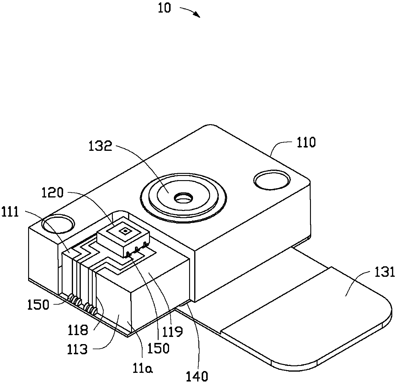
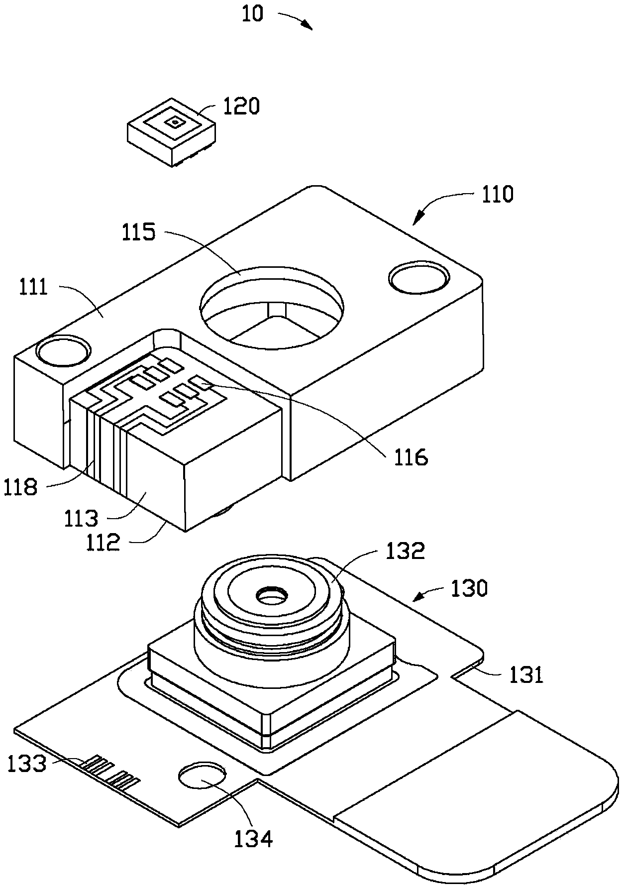
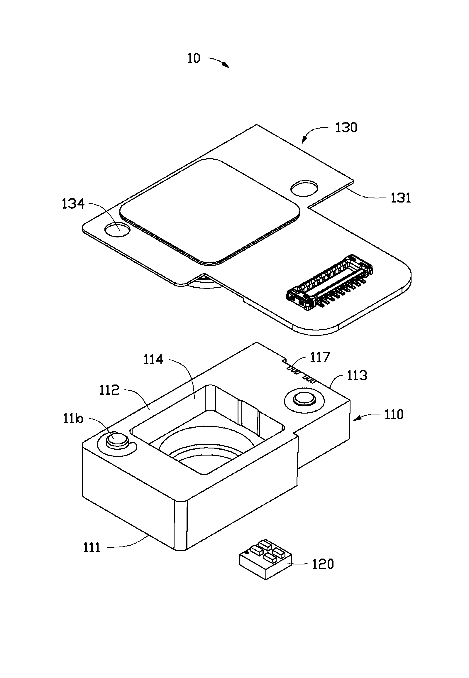
[0026] see Figure 1-3 , the camera module 10 of the preferred embodiment of the present invention includes a casing 110 , an ambient light sensor 120 and a lens module 130 . The housing 110 includes a top surface 111 , a bottom surface 112 opposite to the top surface 111 , and a side surface 113 connecting the top surface 111 and the bottom surface 112 . The housing 110 defines a receiving groove 114 on the bottom surface 112 and defines a through hole 115 communicating with the receiving groove 114 on the top surface 111 . The shell 110 forms a solder seat 116 on the top surface 111 near the side 113 by laser directing structure (LDS), forms a first connector 117 on the bottom 112 near the side 113, and A circuit 118 connecting the solder socket 116 and the first connector 117 is formed on the side surface 113 . The ambient light sensor 120 is welded on the socket 116 . The lens module 130 includes a circuit board 131 (such as a flexible circuit board) attached to the bot...


PUM


Abstract

The invention provides a camera module comprising a housing, an ambient light sensor and a lens module; the housing comprises a top surface, a bottom surface opposite to the top surface, and a side face connecting the top surface with the bottom surface; the bottom surface is provided with a containing slot and the top surface is provided with a through hole connected with the containing slot; a welding seat is formed on a position, close to the side face, of the top surface of the housing through a laser direct formation technology; a first connector is formed on a position, close to the side face, of the bottom surface of the housing through a laser direct formation technology; a circuit connecting the welding seat with the first connector is formed on the side face; the ambient light sensor is welded on the welding seat; the lens module comprises a circuit board attached with the bottom surface and a lens arranged on the circuit board; the lens is contained in the containing slot and exposed outside the through hole; a second connector is formed and matched with the first connector, and welded with the first connector. The assembling of the camera module can be simplified; the invention also provides a making method of the camera module.

Description

technical field [0001] The invention relates to a camera module and a manufacturing method thereof. Background technique [0002] At present, many electronic devices with displays are equipped with ambient light sensors (ALS) for sensing the brightness of ambient light, and accordingly adjust the brightness of the display to provide comfortable viewing effect and save power. For the convenience of production, considering that many electronic devices are generally equipped with a camera module, the ALS can be integrated into the camera module. Specifically, the ALS is set on the flexible circuit board at the bottom of the camera module to connect with the external circuit, and then the part of the flexible circuit board with the ALS is wound around and assembled on the front end of the camera module by using the flexibility of the flexible circuit board to be used During the process, the exposed electronic device senses the brightness of the ambient light. However, such an ...

Claims


Application Information

Patent Timeline
Patent Type & Authority Applications(China)
IPC IPC(8): G03B17/12G02B7/02
CPCG01J1/0411H04N5/2254G01J1/4204H04N5/2252H04N5/2257H04N23/51H04N23/57H04N23/55
Inventor 陈信文
Owner HONG FU JIN PRECISION IND (SHENZHEN) CO LTD
Learn More