
Thin film transistor, array substrate and display device

A technology of thin film transistors and array substrates, applied in the field of liquid crystal display, can solve the problems of long channel length and low working efficiency of thin film transistors, and achieve the effects of shortening charging time, improving working efficiency and reducing area

Inactive Publication Date: 2014-10-08
BOE TECH GRP CO LTD
View PDF6 Cites 11 Cited by
  • Summary
  • Abstract
  • Description
  • Claims
  • Application Information

AI Technical Summary

Problems solved by technology

[0004] According to the above, due to the limitation of the manufacturing process, the channel length is at least 15um, resulting in a long channel length of the thin film transistor and low working efficiency.

Method used


Image

  • Thin film transistor, array substrate and display device
  • Thin film transistor, array substrate and display device
  • Thin film transistor, array substrate and display device

Examples


Embodiment 1

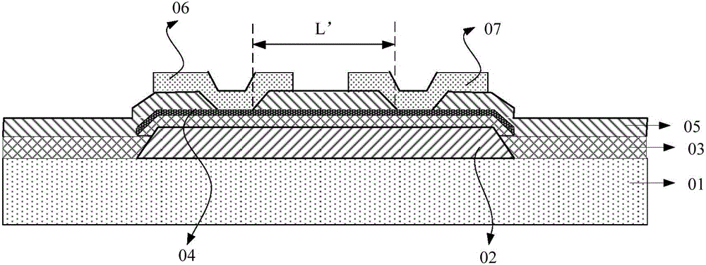
[0048] This embodiment provides a kind of thin film transistor, its structural diagram is as follows figure 2 As shown, including the gate 02, the source 07, the drain 06 and the semiconductor layer 04, the source 07 and the drain 06 are arranged in different layers, the semiconductor layer 04 is electrically connected to the source 07 and the drain 06 respectively, and the semiconductor layer 04 The region between the corresponding source 07 and the drain 06 is the channel region.

[0049] Since the source and the drain are not in the same layer, the channel length between the source and the drain ( figure 2 The middle L represents the channel length) is greatly shortened, and the channel length can be shortened to less than 5um with the current general process precision. Shortening the channel distance can shorten the charging time, greatly improve the charging efficiency of the thin film transistor, and thus improve the working efficiency of the transistor .

[0050] Th...

Embodiment 2

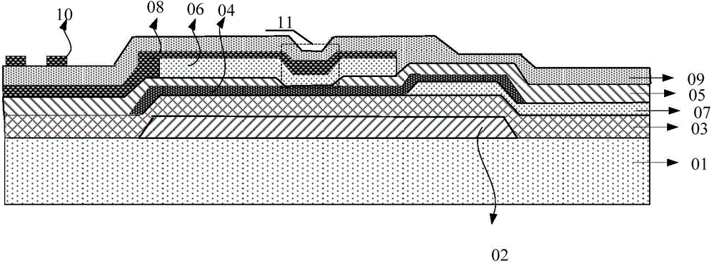
[0059] An embodiment of the present invention provides an array substrate, the structure schematic diagram is as follows image 3 As shown, it includes a base substrate 01, a thin film transistor, a pixel electrode 08, a gate line and a data line (wherein the gate line and the data line are in image 3 not shown), the thin film transistor and the gate line are arranged on the base substrate 01, and the source 07 and the drain 06 of the thin film transistor are arranged in different layers; the semiconductor layer 04 of the thin film transistor is electrically connected to the source 07 and the drain 06 respectively connection; the pixel electrode 08 is electrically connected to the drain 06 of the thin film transistor; the source 07 of the thin film transistor is electrically connected to the data line.

[0060] Preferably, the different layer settings of the source 07 and the drain 06 of the thin film transistor in this embodiment specifically include:

[0061] The source 07...

Embodiment 3

[0084] Embodiment 3 of the present invention also provides a display device, including a color filter substrate and an array substrate, wherein the array substrate is the array substrate described in Embodiment 2.

[0085] The above-mentioned display device can be: OLED panel, TV, digital photo frame, mobile phone, tablet computer and other products or components with any display function.


PUM


Abstract

The invention discloses a thin film transistor, an array substrate and a display device. The thin film transistor comprises a grid electrode, a source electrode, a drain electrode and a semiconductor layer, wherein the source electrode and the drain electrode are arranged on different layers, the semiconductor layer is electrically connected with the source electrode and the drain electrode, and a channel region is formed on the portion, corresponding to the region between the source electrode and the drain electrode, of the semiconductor layer. The invention further provides the array substrate comprising the thin film transistor and the display device. According to the array substrate comprising the thin film transistor and the display device, the source electrode and the drain electrode are made to be formed on different layers by changing the pattern composition technology, a channel, which is originally 15-micron long, of the thin film transistor is reduced to be smaller than 5 microns at present, the resistance of the channel is greatly reduced, the charging efficiency of the thin film transistor can be greatly improved by reducing the length of the channel, charging time is shortened, and thus the working efficiency of the transistor is improved. Due to the fact that the size of the channel of the transistor is reduced, the area of the transistor can also be reduced, and products which are high in integration level can be obtained easily.

Description

technical field [0001] The invention relates to the field of liquid crystal display, in particular to a thin film transistor, an array substrate and a display device. Background technique [0002] Currently in the liquid crystal display industry, the application of Thin Film Transistor Liquid Crystal Display (TFT-LCD for short) is more and more favored by customers. [0003] The structure diagram of the thin film transistor in the liquid crystal display in the prior art is as follows figure 1 As shown, it includes a base substrate 01 and a gate 02 formed on the base substrate 01 , and the gate 02 is covered with a gate insulating layer 03 . A semiconductor layer 04 is also formed above the gate insulating layer 03 , this layer corresponds to the gate 02 and is located above the gate 02 . An etching stopper layer 05 is formed above the semiconductor layer 04, and a source-drain metal layer is formed above the etch stopper layer 05, and a drain electrode 06 and a source elec...

Claims


Application Information

Patent Timeline
Patent Type & Authority Applications(China)
IPC IPC(8): H01L29/786H01L27/12
CPCH01L27/124H01L29/41733H01L29/4175H01L29/78669H01L29/78678H01L29/7869H01L29/78696H01L29/786H01L27/1214H01L29/41758
Inventor 金熙哲宋泳锡刘圣烈崔承镇
Owner BOE TECH GRP CO LTD
Learn More