Position sensitive detector for higher energy heavy ion beam diagnosis
A technology of heavy ion beams and detectors, which is applied in the structural field of position measurement detectors, can solve the problems of fluorescent targets that are difficult to give quantitative results and low sensitivity, and achieve good social effects and improve beam quality.
- Summary
- Abstract
- Description
- Claims
- Application Information
AI Technical Summary
Problems solved by technology
Method used
Image
Examples
Embodiment 1
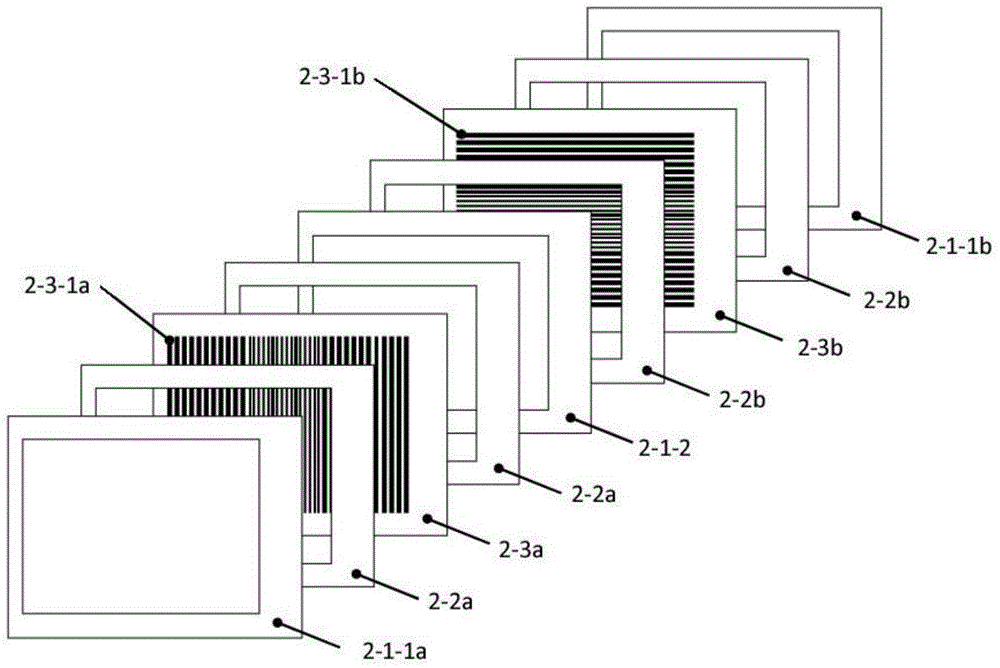
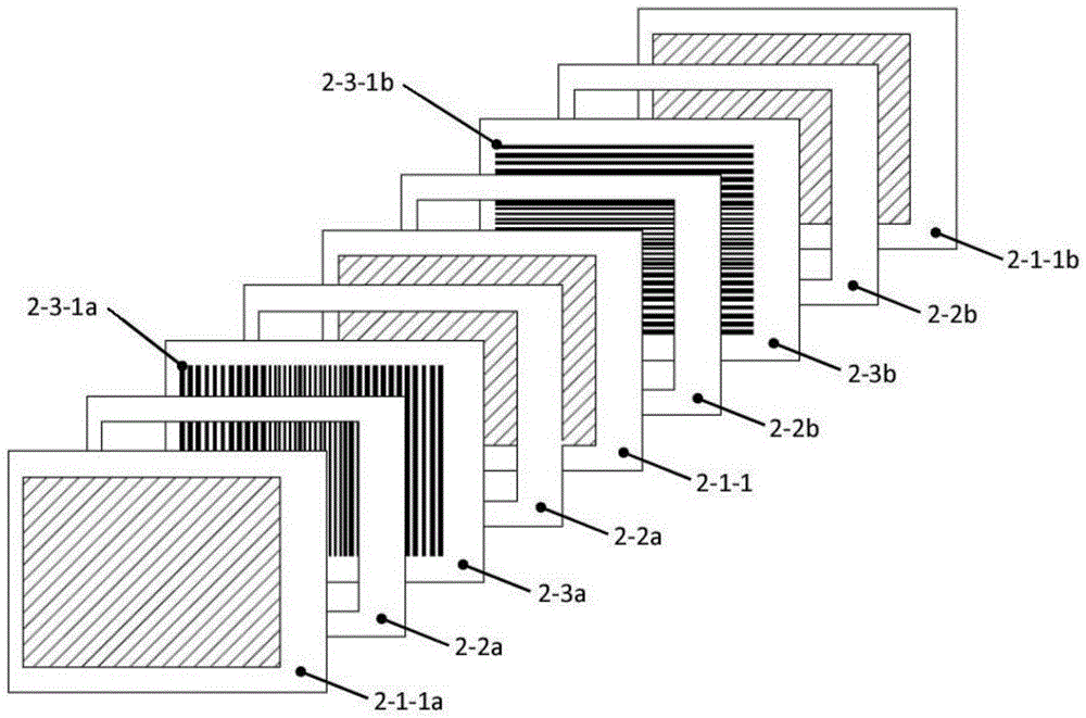
[0047] Example 1: see figure 1 , 2 , 4, 5, 6, 7, a position-sensitive detector for high-energy heavy ion beam diagnosis, including a gas-sealed chamber 1 with a beam probe 2, and the beam probe 2 is fixedly connected to the port seal On the fixed bracket 3-1 of the flange assembly 3; the gas sealing chamber 1 includes an incident window 1-2 on one side of the gas box 1-1, and an exit window 1-3 on the other side; a beam probe 2 consists of two sets of beam current measurement units, each set of beam current measurement units is composed of high voltage poles 2-1, insulating backing plates 2-2 and signal poles 2-3 arranged in sequence; the port sealing flange assembly 3 consists of a fixed bracket 3- 1 and the port sealing flange 3-2; the multi-channel signal lead-out adapter plate 4 includes the multi-channel signal lead-out plate 4-1 and the multi-channel signal adapter plate 4-2; the multi-channel signal adapter plate 4-2 One end is provided with a contact end 4-2-1 insert...
Embodiment 2
[0057] Example 2: see figure 1 , 2 , 4, 5, 6, 7, a position sensitive detector for higher energy heavy ion beam diagnostics.
[0058] The signal pole 2-3 of the beam probe 2 has an effective area of 74×100mm 2 , and a multi-channel signal strip 2-3-1 designed on a hard PCB board with a thickness of 0.2mm. 0.3mm and 1.6mm, the thickness of 35μm copper foil connections, wherein the distance between each signal bar 2-3-1 is 0.2mm and 0.4mm.
[0059] The two groups of beam current measurement units in the beam probe 2, the signal bar 2-3-1a on the first group of signal poles 2-3a and the signal bar 2-3 on the second group of signal poles 2-3b The directions of -1b are perpendicular to each other.
[0060] The high voltage pole 2-1-1 in the beam probe 2 structure has an effective area of 74×100mm 2 The conductive film, whose film frame is composed of epoxy resin aluminum-plated plate frame with conductive electrodes, wherein the thickness of the conductive film is a single...
Embodiment 3
[0067] Embodiment 3: see figure 1 , 2, 4, 5, 6, 7, a position-sensitive detector for high-energy heavy ion beam diagnosis, including a gas-sealed chamber 1 with a beam probe 2, and the beam probe 2 is fixedly connected to the port seal On the fixed bracket 3-1 of the flange assembly 3; the gas sealing chamber 1 includes an incident window 1-2 on one side of the gas box 1-1, and an exit window 1-3 on the other side; a beam probe 2 consists of two sets of beam current measurement units, each set of beam current measurement units is composed of high voltage poles 2-1, insulating backing plates 2-2 and signal poles 2-3 arranged in sequence; the port sealing flange assembly 3 consists of a fixed bracket 3- 1 and the port sealing flange 3-2; the multi-channel signal lead-out adapter plate 4 includes the multi-channel signal lead-out plate 4-1 and the multi-channel signal adapter plate 4-2; the multi-channel signal adapter plate 4-2 One end is provided with a contact end 4-2-1 inse...
PUM
| Property | Measurement | Unit |
|---|---|---|
| Thickness | aaaaa | aaaaa |
| Width | aaaaa | aaaaa |
| Thickness | aaaaa | aaaaa |
Abstract
Description
Claims
Application Information
 - R&D
- Intellectual Property
- Life Sciences
- Materials
- Tech Scout
- Unparalleled Data Quality
- Higher Quality Content
- 60% Fewer Hallucinations
Browse by: Latest US Patents, China's latest patents, Technical Efficacy Thesaurus, Application Domain, Technology Topic, Popular Technical Reports.
© 2025 PatSnap. All rights reserved.Legal|Privacy policy|Modern Slavery Act Transparency Statement|Sitemap|About US| Contact US: help@patsnap.com


