
Continuously variable transmission for direct control mode crawler

A continuously variable transmission, vehicle technology, applied in belts/chains/gears, transmission parts, gear transmissions, etc., can solve the problems of low steering precision and poor steering maneuverability, and achieve the effect of simple and convenient operation

Inactive Publication Date: 2014-10-08
HUNAN AGRICULTURAL UNIV
View PDF6 Cites 14 Cited by
  • Summary
  • Abstract
  • Description
  • Claims
  • Application Information

AI Technical Summary

Problems solved by technology

[0003] At the same time, the crawler tractor vehicles on the market usually adopt the steering scheme of the steering rod to operate the jaw clutch and the multi-disc brake. The realization process is: when the crawler tractor vehicle turns left, the driver operates the left steering rod to make The left jaw clutch is separated and the left output shaft is braked. Since the transmission power on the left side of the crawler tractor is interrupted and braked to stop the rotation, at this time, driven by the power on the right side of the tractor, the implement turns to the left; the same reason Right side steering can be realized, but this kind of steering mechanism is realized by separating and combining jaw clutch and brake, which has low steering precision and poor steering controllability;

Method used


Image

  • Continuously variable transmission for direct control mode crawler
  • Continuously variable transmission for direct control mode crawler
  • Continuously variable transmission for direct control mode crawler

Examples


Embodiment Construction

[0047] In order to make the technical means, creative features, goals and effects achieved by the present invention easy to understand, the present invention will be further described below in conjunction with specific illustrations.

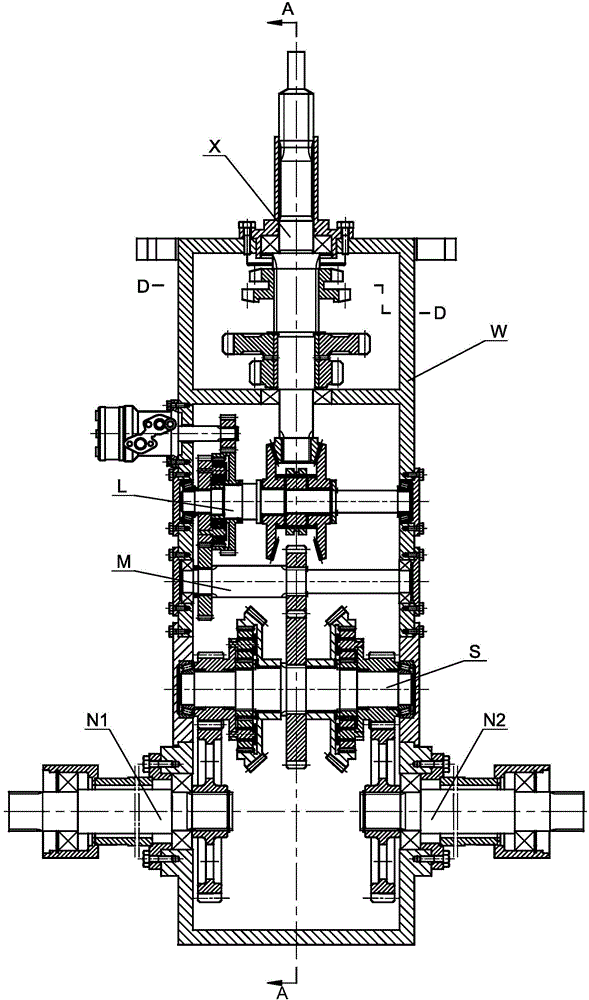
[0048] see Figure 1 ~ Figure 2 The direct-controlled continuously variable transmission for tracked vehicles includes a power input part X, a power output shaft deceleration part Y, a power output shaft part Z, a box W, a forward and reverse continuously variable transmission part L, a forward and reverse gear control part T, and a power output Shaft shifting part U, intermediate power transmission part M, external control connection part R, differential planetary transmission part S, left crawler driving part N1 and right crawler driving part N2; among them, the power input part X and the power output shaft decelerate Part Y, power output shaft part Z, forward and reverse continuously variable transmission part L, forward and reverse gear cont...


PUM


Abstract

The invention provides a continuously variable transmission for a direct control mode crawler. A part of power of a power input part is transmitted to a power output shaft part through a speed reduction part of the power output shaft and used for external operation, and the other part of the power is transmitted to an advancing and retreating gear stepless speed change part. The advancing and retreating gear stepless speed change part is connected with a differential planetary transmission part through a middle power transmission part, the power is output to a left side track drive part and a right side track drive part through the differential planetary transmission part, and a power output shaft gear shifting part controls the power output part to output the power to the speed reduction part of the power output shaft; an advancing and retreating gear control part controls gear shifting of the advancing and retreating gear stepless speed change part, and an external control connecting part is connected with the differential planetary transmission part and used for achieving direct control and steering. According to the continuously variable transmission, a self-locking type hydraulic motor is adopted for controlling a planetary frame of a planetary gear transmission mechanism so as to achieve mechanical direct drive and hydraulic steplesss speed adjustment; meanwhile, a direct control mode is adopted for differential drive, the control precision and the response feature are effectively improved, the transmission efficiency is high, operation is easy and convenient, and steering is convenient.

Description

technical field [0001] The invention relates to the technical field of agricultural machinery transmission, in particular to a direct-controlled continuously variable transmission for crawler vehicles. Background technique [0002] Tracked vehicles are mainly crawler tractors, and crawler tractors usually use a purely mechanical power transmission system to transmit power, which has the advantages of simple structure and high efficiency. Usually do not have the skills to drive a car or tractor, and it is difficult to control the coordination of clutch, accelerator and gear shift, which limits the development of tractors. At present, many crawler tractor manufacturers have adopted the hydraulic pump-motor integrated system to realize the stepless driving system of the crawler tractor. Since the driving operability of the crawler tractor with the stepless driving system has been improved, agricultural machinery operators do not need to participate in professional technical tra...

Claims


Application Information

Patent Timeline
Patent Type & Authority Applications(China)
IPC IPC(8): F16H57/023F16H3/76
CPCF16H47/04
Inventor 孙松林肖名涛谢方平蒋蘋吴明亮
Owner HUNAN AGRICULTURAL UNIV
Learn More