Optimization connecting structure of metal pipe fittings and implementation method thereof

A technology for connection structures and metal pipe fittings, which is applied in the connection of rods, connection components, metal processing equipment, etc., can solve the problems of small connection volume, connection strength and toughness decline, and achieve good toughness, increased safety, and comfort sexual effect

Active Publication Date: 2014-10-08
黄有志
View PDF6 Cites 7 Cited by
  • Summary
  • Abstract
  • Description
  • Claims
  • Application Information

AI Technical Summary

Problems solved by technology

[0005] The present invention aims at problems such as slag inclusion, shrinkage cavity, cracks, greatly reduced connection strength and toughness, and too small connection volume in the existing welding process of metal pipe fittings; it provides an optimized connection structure of metal pipe fittings and its realization method: it adopts in There is a radial through hole around the end of the pipe fitting, and a multi-functional plug is inserted into the inner hole of the end of the pipe; one or more pipe fittings that have been inserted into the plug are used as the inlay of the connecting piece, and placed in advance After fastening the corresponding position of the casting and forging mold under the connector, the mold is closed, and then under the PLC control of the casting and forging compound machine, when the laminar flow filling process is performed on the cavity of the connector, the metal fluid injected into the cavity of the connector can be Through the radial through hole of the pipe fitting and the axial through hole of the plug head, it flows into the groove of the plug head. After the connecting piece is extruded and forged, two metal rings of the inner layer and the outer layer are formed, and the connecting part of the pipe to be connected and the plug head is formed. , Wrap and forge the connecting structure in three dimensions, so as to complete the high-strength connection between the connecting piece and the pipe fitting

Method used


Image

  • Optimization connecting structure of metal pipe fittings and implementation method thereof
  • Optimization connecting structure of metal pipe fittings and implementation method thereof
  • Optimization connecting structure of metal pipe fittings and implementation method thereof

Examples


Embodiment 1

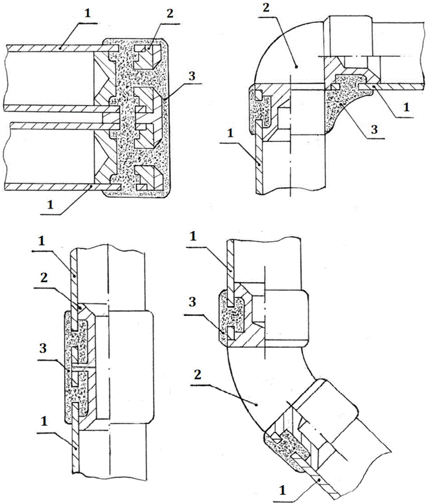
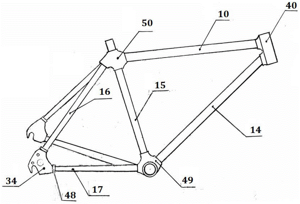
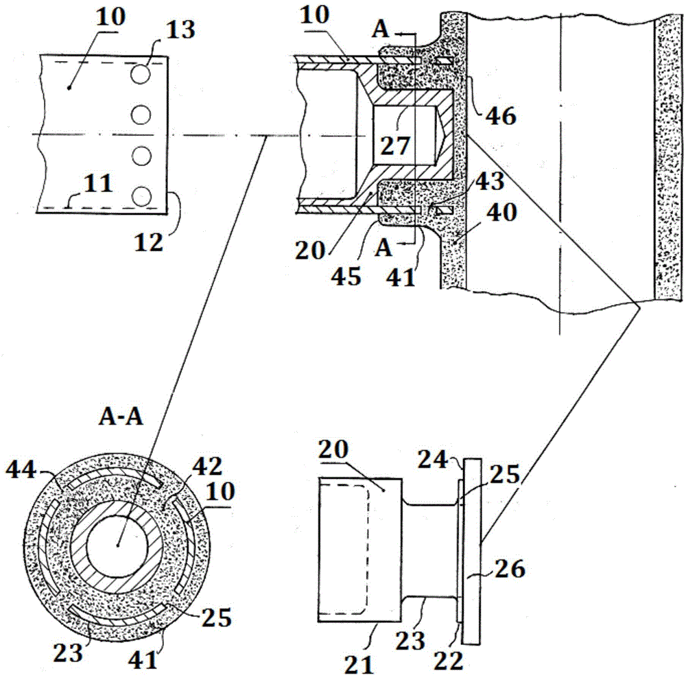
[0059] Example 1. See figure 2 , image 3 , Figure 4 , the high-strength connection between the front tube 40 of the frame and the upper tube 10 and the lower tube 14 and the combined configuration of the tube material:

[0060] 1.1) The upper tube 10 and the lower tube 14 adopt Ti3AL2.5V titanium alloy seamless round tube, the wall thickness = 0.8mm, the inner hole = 30.0mm; the peripheral through hole of the connecting end of the upper tube 10 and the lower tube 14 is processed by mechanical or laser = 7.0mm, quantity = 6 pieces; the front pipe 40, plugs 20 and 28 are made of AZ80A‐T4 and T6 magnesium ingots and rods respectively, the former is processed by casting and forging composite machine, and the latter is processed by lathe.

[0061] 1.2) Chamfer, deburr, clean and dry the sharp edges of pipe fittings and plugs.

[0062] 1.3) Carry out micro-arc oxidation insulation treatment on the surface of the plug.

[0063] 1.4) Plug the plugs 20 and 28 into the inner hole...

Embodiment 2

[0066] see figure 2 , image 3 , Figure 5 , the high-strength connection between the frame riser joint 50, the upper tube 10 and the upper fork 16, and the material combination configuration of the pipe fittings:

[0067]2.1) In the inner hole of the connection part at the upper end of the standpipe 15, the axial length = 50.0mm, the pipe thickness increased = 1.0mm, and the local diameter expansion process was increased by 8.0mm: Then connect the upper pipe 10 and the upper fork 16 At the center position, the through-holes 51 and 52 through which the upper tube 10 and the upper fork 16 can enter are oppositely processed; the width of the inner hole of the upper fork 16 is 12.1 mm, and the thickness 30 of the plug body at the end of the flat corner joint 29 is 12.0 mm. mm, the sliding fit clearance between the two is 0.1mm, and the thickness of the middle end and the top end is 7.0mm. Except that the upper pipe 10 is made of Ti3AL2.5V titanium alloy seamless pipe, the res...

Embodiment 3

[0073] see Figure 7 , Figure 9 , the high-strength connection of the shoulder cover joint 58 and the front fork vertical tube 60 and two left and right front fork tubes 62 and the combined configuration of the pipe fitting material:

[0074] 3.1) The two front fork tubes 61 are made of Ti3AL2.5V titanium alloy seamless pipe, and the rest of the vertical pipe 60, plug head 20, shoulder cap double plug head 38 and shoulder cap joint 58 are respectively made of 7050-T4 and T6 aluminum alloy seamless pipes , bars and ingots.

[0075] 3.2) Chamfer, deburr, clean and dry the sharp edges of pipe fittings and plugs.

[0076] 3.3) Perform micro-arc oxidation insulation treatment on the surface of pipe fittings and plugs.

[0077] 3.4) Insert the plug head 20 into the inner hole of the connecting end of the vertical pipe 60, then place it in the positioning circular groove 35 of the double plug head 38 of the shoulder cover, and connect the axial through hole 25 of the plug head wi...


PUM

PropertyMeasurementUnit
thicknessaaaaaaaaaa

Abstract

The invention relates to the technical field of metal pipe fitting connection, in particular to an optimization connecting structure of metal pipe fittings and an implementation method thereof. The structure comprises the pipe fittings, multi-functional plugs arranged in inner holes in the tail ends of the pipe fittings, and connecting pieces connecting the pipe fittings. The peripheries of the connecting portions of the pipe fittings are provided with radial through holes, and a center connecting line of the through holes is parallel to the end faces of the pipe fittings. Each multifunctional plug comprises a plug body at the tail end, a groove or through hole in the middle, a large positioning step and a small positioning step which are located at the top end, wherein the outer end face of the large step is provided with an axial through hole or through groove communicated with the groove. Each connecting piece is of a casting-forging composite structure, and inner and outer layers of metal rings and a plurality of radial and axial metal posts connected with the metal rings are formed through forming carried out in a casting-forging mold. Pipe fitting and plug forging connection portions machined in a casting-forging mode are covered and connected in a forging mode in the three-dimensional direction to form an integral structure. High-toughness connection of a bicycle frame and pipe fittings of a front fork is thoroughly achieved.

Description

technical field [0001] The invention relates to the technical field of connection of metal pipe fittings, in particular to a high-strength and tough connection structure for various frame pipe fittings and its realization method. Background technique [0002] At present, in the light motor vehicle or non-motor vehicle manufacturing industry in the world, in order to pursue energy saving, emission reduction and light weight, most of them choose light metal hollow thin-walled pipes and connect them into frames or other products through welding process. The advantage of this connection is that the equipment is simple, The investment is small, and the product style changes quickly. The disadvantage is that the connection strength and toughness are greatly reduced, and there are potential safety hazards. The reason: the weld is a cast-state coarse-grained structure, which is prone to slag inclusions, shrinkage cavities, cracks, and too small volumes of pipe fittings involved in t...

Claims


Application Information

Patent Timeline
Patent Type & Authority Applications(China)
IPC IPC(8): B62K19/18F16B7/00
CPCB21K25/00B21C37/28B21J5/002B23P15/00B62K3/02B62K19/06B62K19/28F16B17/004B62K19/18F16B7/00
Inventor 黄启达
Owner 黄有志
Why Eureka
Try Eureka