Magnetic separator

A magnetic separator and chassis technology, applied in the field of magnetic separators, can solve the problems of wear of magnetic separators, complicated manufacturing process and high manufacturing cost, and achieve the effect of prolonging service life, simple manufacturing process and reducing manufacturing cost.

Inactive Publication Date: 2014-10-08
潘纪鸿
View PDF10 Cites 0 Cited by
  • Summary
  • Abstract
  • Description
  • Claims
  • Application Information

AI Technical Summary

Problems solved by technology

[0002] The existing magnetic separator generally needs to use a scraper or other stripping parts to remove material from the magnetic separation cylinder. While removing material, the friction between the scraper and the magnetic separation cylinder is easy to cause wear of the magnetic separation cylinder. , while the production process is complex and the production cost is high

Method used


Image

  • Magnetic separator

Examples


Embodiment Construction

[0015] The principles and features of the present invention are described below in conjunction with the accompanying drawings, and the examples given are only used to explain the present invention, and are not intended to limit the scope of the present invention.

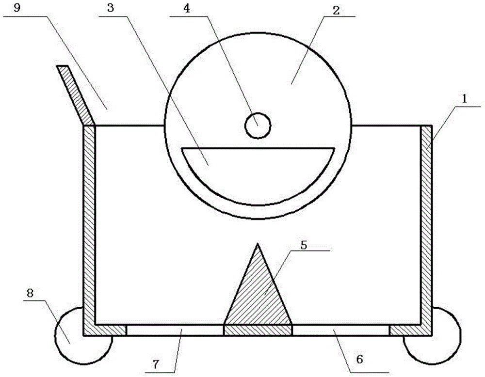
[0016] Such as figure 1 Shown, a kind of magnetic separator comprises cabinet 1, drum 2, magnet 3, rotating shaft 4 and universal wheel 8, and described drum 2 is installed in the middle position of described cabinet 1 top by described rotating shaft 4, and described drum 2 is a hollow cylindrical structure, and the magnet 3 is fixedly installed in the lower half of the inside of the drum 2 . The upper part of the cabinet 1 is provided with a feed port 9, and after the drum 2 is started to rotate, the ore to be selected enters the cabinet 1 from the feed port 9, and the concentrate adheres to the surface of the drum 2 under the action of the magnetic force of the magnet 3 , and the concentrate moves with the rotati...


PUM


Abstract

The invention relates to a magnetic separator, comprising a case, a roller, a rotating shaft and universal wheels, wherein the roller is installed at a middle position of the upper part of the case through the rotating shaft; the roller is in a hollow cylindrical structure; the lower half in the roller is fixedly provided with the magnet; a feeding opening is disposed on the upper part of the case at the side of the roller; and one side of the lower part of the case is provided with a tailings discharging opening; the other side of the lower part of the case is provided with a concentrate discharging opening; and the universal wheels are fixedly connected to the bottom of the case. The magnetic separator provided by the invention is in no need of arranging a special demineralization structure, and can discharge materials automatically through the rotation of the roller. A manufacturing process is simple; manufacturing cost is reduced; and the service life is prolonged.

Description

technical field [0001] The invention relates to the field of mineral processing, in particular to a magnetic separator. Background technique [0002] The existing magnetic separator generally needs to use a scraper or other stripping parts to remove material from the magnetic separation cylinder. While removing material, the friction between the scraper and the magnetic separation cylinder is easy to cause wear of the magnetic separation cylinder. , while the manufacturing process is complicated and the manufacturing cost is also high. Contents of the invention [0003] In order to solve the above problems, the technical problem to be solved by the present invention is to provide a magnetic separator. [0004] The technical solution of the present invention to solve the above-mentioned technical problems is as follows: a magnetic separator, comprising a casing, a drum, a magnet, a rotating shaft and a universal wheel, the drum is installed in the middle of the upper part ...

Claims


Application Information

Patent Timeline
Patent Type & Authority Applications(China)
IPC IPC(8): B03C1/14
Inventor 潘纪鸿
Owner 潘纪鸿
Why Eureka
Try Eureka