
Filter core type deduster and control method thereof

A dust collector and filter element technology, applied in chemical instruments and methods, separation methods, dispersed particle filtration, etc., can solve the problems of easy blockage of the filter device, incomplete dust filtration, troublesome cleaning of the filter device, etc., and achieve the effect of improving accuracy.

Inactive Publication Date: 2014-10-08
柏司得环保科技(上海)有限公司
View PDF7 Cites 8 Cited by
  • Summary
  • Abstract
  • Description
  • Claims
  • Application Information

AI Technical Summary

Problems solved by technology

[0007] In order to overcome the technical problems of incomplete dust filtration in the prior art, troublesome cleaning of the filter device, and easy blockage of the filter device, the inventor has completed the present invention after conducting a large amount of in-depth research.

Method used


Image

  • Filter core type deduster and control method thereof
  • Filter core type deduster and control method thereof
  • Filter core type deduster and control method thereof

Examples


Embodiment 1

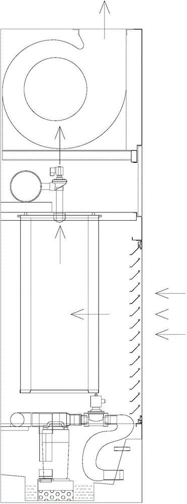
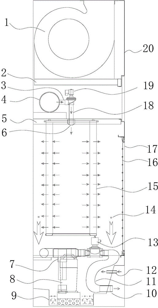
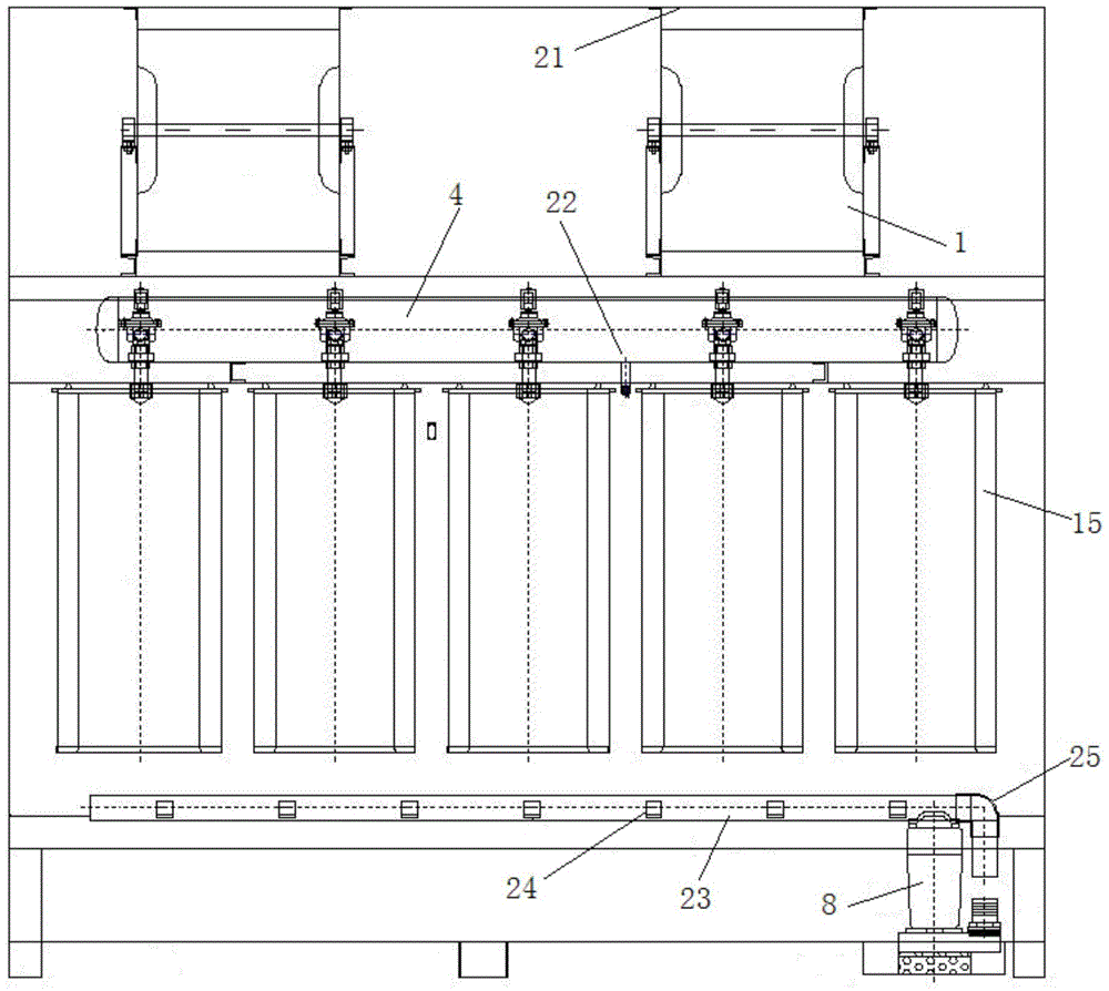
[0032] This embodiment relates to a filter element type dust collector, such as figure 1 , figure 2 , image 3 and Figure 4 As shown, it includes a cabinet body 20, a fan 1 and a dirt accumulation tank 9, the fan 1 is arranged on the top of the cabinet body 20 through the fan support plate 2, the top surface of the fan 1 is provided with an air outlet 21, and the dirt accumulation tank 9 is arranged on the cabinet body At the bottom of 20, a filter element 15 is arranged between the blower fan 1 and the dirt tank 9, and a cylindrical porous fiber filter element can be used. The filter element 15 is fixed on the inside of the cabinet 20 by the filter element mounting plate 5, and the bottom end of the filter element 15 is closed. The middle part of the top is provided with a through hole, and the through hole is equipped with a blowing explosion head 6, and the blowing explosion head 6 is connected with a pulse valve 19 through a blowing pipe 18, and the filter element moun...

Embodiment 2

[0041] The difference between this embodiment and embodiment 1 is: as Figure 5 As shown, the water inlet and outlet are set on the opposite side of the sewage tank, and the height of the water inlet is greater than the height of the water outlet. Firstly, the water inlet is connected to the self-contained water source. , The drain valve is always open, so that after the water entering the dirt tank fully washes the dust, the dust and water form mud and then flow out from the water outlet, realizing the self-circulation flushing of the dirt tank without manual cleaning, which is very convenient. In the case of a production workshop with drainage ditches and sedimentation tanks, the mud can automatically flow to the drainage ditch; in the case of no drainage ditches in the production workshop, the sewage pump can be controlled by one key through the circuit, and it can be directly discharged to the further sedimentation through the pipeline pool.

Embodiment 3

[0043] The difference between this embodiment and embodiment 1 is that the dry powder collection type is used to directly recover dust or highly polluted dust, such as Figure 6 As shown, there is no water in the dirt tank at the bottom of the cabinet, and the dust deposited on the outer surface of the filter element falls off and settles in the bottom dirt tank of the cabinet, and then the dust at the bottom can be directly recovered, especially suitable for dust with special properties , such as dust that is likely to cause water pollution.


PUM


Abstract

The invention relates to a filter core type deduster and a control method thereof. The filter core type deduster comprises a cabinet, a fan and a dirt accumulating tank, wherein the fan is arranged on the top of the cabinet through a fan support plate, the dirt accumulating tank is arranged at the bottom of the cabinet, a filter core is arranged between the fan and the dirt accumulating tank and is fixed in the cabinet through a filter core installing plate, the bottom end of the filter core is enclosed, the top end of the filter core is provided with a through hole, a blowing blasting head is installed in the through hole and is connected with a pulse valve through a blowing pipe, a cylinder is arranged between the filter core installing plate and the fan support plate and is connected with the pulse valve through a cylinder air outlet pipe, one side of the cabinet is provided with a dust absorbing port, and the dust absorbing port is provided with, from interior to exterior, an air inlet gauze and an air inlet shutter. The filter core type deduster can completely remove dust in dust-containing air and allows dust filtering to be more thorough, ash in the filter core can be easily removed, the filter core is hardly to obstruct and has high filtering efficiency, so the filter core type deduster can be widely applied to removal of industrial dust.

Description

technical field [0001] The invention relates to a dust collector and a control method thereof, in particular to a filter element type dust collector and a control method thereof. Background technique [0002] In the process of industrial production, a large amount of industrial dust is often produced, which will cause great harm to the working environment and human health. Therefore, effective control of industrial dust must be imposed, which is very important for enterprise development and environmental pollution control. meaning. [0003] CN202590569U (disclosed on December 12, 2012) discloses a dust removal cabinet, comprising a cabinet body, a water curtain filter, a fan, a water storage tank, and an electrical control box. The water curtain filter is composed of a water pump, a water pipe, and an overflow tank , a filter device and a partition plate, the overflow tank is located at the top of the filter device; the water pump communicates with the overflow tank through...

Claims


Application Information

Patent Timeline
Patent Type & Authority Applications(China)
IPC IPC(8): B01D50/00B01D46/24
Inventor 杨建平
Owner 柏司得环保科技(上海)有限公司
Learn More