


Quick Research
Generate reliable direction feasibility study reports for your R&D in just a few steps.

Technical Q&A
Discover and master advanced knowledge NOW. Basics, ideas, possibilities, all at once.

Find Solutions
As an expert in R&D theories, this can generate solutions to your technical problems instantly.

Evaluate Feasibility
Analyze your overall solution with one click, know your potential R&D risks in advance.

Monitor Landscape
Get weekly tech updates, stay abreast of the latest tech innovations and key insights.
Novel heat pump distillation energy saving process for desulfurization solvent in regenerable flue gas desulfurization
A technology for regenerating flue gas and heat pump distillation, which is used in steam distillation, flash distillation, heating water/sewage treatment, etc. It can solve the problems of insufficient heat recovery, high material grade requirements, and high reboiler operating pressure, and reduce distillation. The effect of reducing energy consumption, improving energy utilization rate and reducing heat exchange area
- Summary
- Abstract
- Description
- Claims
- Application Information
AI Technical Summary
Problems solved by technology
Method used
Image

Examples
Embodiment 1
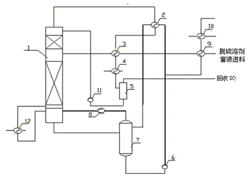
[0038] A new heat pump distillation energy-saving process for desulfurization solvent in renewable flue gas desulfurization, the process steps are as follows:
[0039] A. The self-desulfurization section contains SO2 The rich liquid of the desulfurization solvent is distilled and separated from SO in the distillation tower 2 , the lean liquid at the bottom of the distillation tower is sent to the flash tower, and flashed in the flash tower;
[0040] B. The flash steam generated by flash evaporation is sent into the compressor, and the compressor is used to compress the flash steam to do work;
[0041] C. Send the steam output from the compressor to the bottom of the distillation tower, form the rising steam required for distillation with the vaporized water, and conduct mass transfer and heat transfer with the rich liquid descending from the upper part of the distillation tower to complete the distillation process;
[0042] The part of the lean liquid after flash evaporation ...
Embodiment 2
[0044] A new heat pump distillation energy-saving process for desulfurization solvent in renewable flue gas desulfurization, the process steps are as follows:
[0045] A. The self-desulfurization section contains SO 2 The rich liquid of the desulfurization solvent is distilled and separated from SO in the distillation tower 2 , the lean liquid at the bottom of the distillation tower is sent to the flash tower, and flashed in the flash tower;
[0046] B. The flash steam generated by flash evaporation is sent into the compressor, and the compressor is used to compress the flash steam to do work;
[0047] C. Send the steam output from the compressor to the bottom of the distillation tower, form the rising steam required for distillation with the vaporized water, and conduct mass transfer and heat transfer with the rich liquid descending from the upper part of the distillation tower to complete the distillation process;
[0048] The part of the lean liquid after flash evaporatio...
Embodiment 3
[0050] A new heat pump distillation energy-saving process for desulfurization solvent in renewable flue gas desulfurization, the process steps are as follows:
[0051] A. The self-desulfurization section contains SO 2 The rich liquid of the desulfurization solvent is distilled and separated from SO in the distillation tower 2 , the lean liquid at the bottom of the distillation tower is sent to the flash tower, and flashed in the flash tower;
[0052] B. The flash steam generated by flash evaporation is sent into the compressor, and the compressor is used to compress the flash steam to do work;
[0053] C. Send the steam output from the compressor to the bottom of the distillation tower, form the rising steam required for distillation with the vaporized water, and conduct mass transfer and heat transfer with the rich liquid descending from the upper part of the distillation tower to complete the distillation process;
[0054] The part of the lean liquid after flash evaporatio...
PUM
 Abstract
Description
Claims
Application Information
 - R&D Engineer
- R&D Manager
- IP Professional
- Industry Leading Data Capabilities
- Powerful AI technology
- Patent DNA Extraction
Browse by: Latest US Patents, China's latest patents, Technical Efficacy Thesaurus, Application Domain, Technology Topic, Popular Technical Reports.
© 2024 PatSnap. All rights reserved.Legal|Privacy policy|Modern Slavery Act Transparency Statement|Sitemap|About US| Contact US: help@patsnap.com