Objective lens frame connector

A technology of frame connectors and objective lenses, which is applied in the field of lithography, can solve problems such as amplifying the influence of disturbances, and achieve the effects of avoiding disturbances, improving connection stability, and reducing response

Active Publication Date: 2016-07-06
SHANGHAI MICRO ELECTRONICS EQUIP (GRP) CO LTD
View PDF3 Cites 0 Cited by
  • Summary
  • Abstract
  • Description
  • Claims
  • Application Information

AI Technical Summary

Problems solved by technology

The flexible mechanism can isolate the disturbance force from the low-frequency region of the main substrate, but the disturbance force near the boundary of the low-frequency region will amplify its disturbance effect

Method used


Image

  • Objective lens frame connector
  • Objective lens frame connector
  • Objective lens frame connector

Examples


Embodiment 1

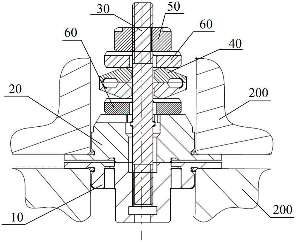
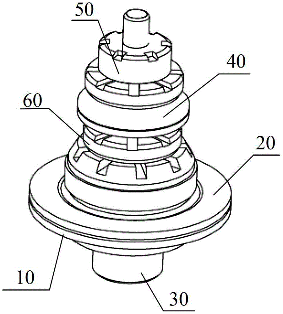
[0032] The objective lens frame connector of the present embodiment, Figure 2-6 As shown, it includes: a flexible base 10 , a flexible cover 20 , stud bolts 30 and butterfly spring sets 40 . Wherein, the flexible base 10 and the flexible cover 20 are connected through the stud bolts 30, and the flexible base 10 and the flexible cover 20 are respectively fixedly connected with the objective lens frame 200, and the butterfly spring group 40 is fixed on the On the above-mentioned stud bolt 30. Specifically, the objective lens frame connector is used for the connection between two objective lens frames 200, the belleville spring group 40 is used to preload the objective lens frame connector, and the stud bolt 30 plays the role of one-way locking, The connection stability of the objective lens frame connector can be improved. Since the studs 30, the flexible base 10 and the flexible cover 20 can be quickly disassembled and installed, each frame surface of the objective lens fram...

Embodiment 2

[0041] The difference between this embodiment and Embodiment 1 lies in the structure of the flexible upper cover.

[0042] Please refer to Figure 7-8 , the flexible base 10' is provided with a flexible connecting ring 80', and the two sides of the flexible connecting ring 80' are respectively provided with flexible lower grooves 90'. Further, a flexible upper groove 100' is also provided on the flexible cover plate 20'. At this time, the axial stiffness of the objective lens frame connector is higher than the shear stiffness, where the axial (Z’) stiffness is 0.1×10 5 N / mm to 10×10 5 Between N / mm, the shear stiffness (R’) is 0.1×10 5 N / mm to 5×10 5 Between N / mm. Specifically, when the axial width of the flexible connecting ring 80' becomes larger, both the axial and shear stiffnesses become larger, and the axial stiffness is most affected; when the position of the flexible connecting ring 80' is along the shear width The axial stiffness and the shear stiffness are both ...


PUM

PropertyMeasurementUnit
stiffnessaaaaaaaaaa

Abstract

The invention discloses an objective lens frame connector, comprising: a flexible base, a flexible cover plate, a stud bolt and a butterfly spring group, the flexible base and the flexible cover plate are connected through the stud bolts, and the flexible base and the flexible cover plate are respectively connected to the The objective lens frame is fixedly connected, and the Belleville spring group is fixed on the stud bolts. Since the stud bolts, the flexible base and the flexible cover can be quickly disassembled and installed, the objective lens frame is easy to install, and also avoids the disturbance effect between the objective lens frame and the internal modules. The flexible base and the flexible cover make the objective lens frame connector have a certain flexibility, which solves the problem that the polyhedral frame enveloping EUV objective lens frame is difficult to assemble. In actual application, according to the size of the objective lens frame, a multi-point contact flexible connection frame structure is designed to ensure that the overall objective lens frame has a certain high rigidity, so as to achieve the high mode of the EUV objective lens frame structure, thereby reducing the low frequency of the connection to the main substrate. Responses to regional perturbations.

Description

technical field [0001] The invention relates to the field of photolithography, in particular to an objective lens frame connector. Background technique [0002] With the continuous decline of lithography resolution in lithography technology, the light source has also developed from deep ultraviolet light to extreme ultraviolet light. Extreme ultraviolet lithography (EUVL) is the most promising next-generation lithography technology for 22nm and below nodes, which has attracted great attention from the global semiconductor industry. [0003] Extreme ultraviolet lithography has become the mainstream development trend of the next-generation lithography industry, causing the structural design of the objective lens to gradually change from a lenticular objective lens to a reflective objective lens. At present, there is an EUVL curved large field of view objective lens composed of six mirrors. The bottom or top of each mirror has an objective lens mount, and the objective lens h...

Claims


Application Information

Patent Timeline
Patent Type & Authority Patents(China)
IPC IPC(8): G03F7/20G02B7/182
Inventor 季采云赵灿武吴飞王璟
Owner SHANGHAI MICRO ELECTRONICS EQUIP (GRP) CO LTD
Why Eureka
Try Eureka