
A flooded air-cooled heat pump unit

An air-cooled heat pump and flooded technology, which is applied in the field of flooded air-cooled heat pump units, can solve the problems of reduced reliability of the unit, stuck valve core, and improper reversing, so as to prevent large fluctuations in water temperature and avoid stuck The effect of reducing the dead and defrosting area

Active Publication Date: 2016-03-23
顿汉布什(中国)工业有限公司
View PDF7 Cites 0 Cited by
  • Summary
  • Abstract
  • Description
  • Claims
  • Application Information

AI Technical Summary

Problems solved by technology

In winter, the defrosting process of the unit is very frequent, and the four-way valve will also operate frequently. If the valve core or cylinder body is slightly worn, there will be quality problems such as improper reversing and valve core stuck. It is a vulnerable part in the heat pump unit and greatly Reduced unit reliability

Method used


Image

  • A flooded air-cooled heat pump unit
  • A flooded air-cooled heat pump unit
  • A flooded air-cooled heat pump unit

Examples


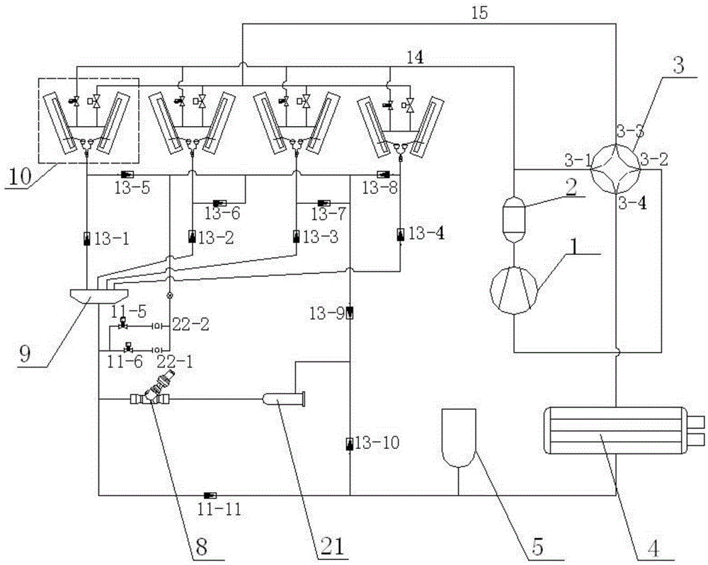
Embodiment 1

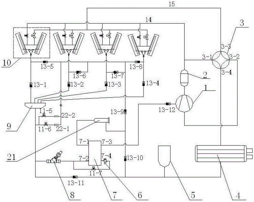
[0021] Example 1, such as figure 2 As shown, a flooded air-cooled heat pump unit includes a compressor 1, a flooded evaporator 4, an electric four-way valve 3, an expansion valve 6, a condensation coil unit 10, an external oil separator 2, a dry filter Device 21, economizer 7, main expansion valve 8, liquid reservoir 5, liquid separator 9.

[0022] The exhaust port of the compressor 1 is connected to the external oil separator 2, and the exhaust gas enters the external oil separator 2 for secondary oil separation to prevent excessive refrigeration oil from entering the system. The external oil separator 2 The outlet pipe is divided into two paths: the main exhaust pipe and the bypass defrosting pipe 14, the main exhaust pipe is connected to the first interface 3-1 of the electric four-way valve 3, and the second interface of the electric four-way valve 3 3-2 is connected to the suction port of the compressor 1, the third port 3-3 is connected to the coil unit, the fourth por...

Embodiment 2

[0028] Example 2, such as figure 1 As shown, there is no economizer 7 and corresponding pipeline parts. The outlet pipeline of the dry filter 21 is directly connected with the inlet of the main expansion valve 8 . The condensed high-pressure liquid does not go through the recooling process of the economizer 7 and directly enters the main expansion valve 8 to throttle and evaporate. Cooling, heating and defrosting are implemented in the same way as in method one. This embodiment is easy to understand for those skilled in the professional field, so it is not repeated here.


PUM


Abstract

The invention relates to a flooded air-cooled heat pump unit, including a compressor, a flooded evaporator, an electric four-way valve, an expansion valve, a main expansion valve, a condensation coil unit, an external oil separator, a dry filter, Liquid storage, liquid separator. The invention adopts segmented defrosting method, which has high defrosting efficiency, short defrosting time and complete defrosting; defrosting a section of coil pipe through hot gas bypass method can effectively prevent large fluctuations in water temperature caused by traditional reverse defrosting, and improve The comfort of air conditioning. There is no cold and heat offset during defrosting, and the energy loss is small, which can significantly improve the energy efficiency ratio of the unit; the defrosting component realizes the defrosting of the unit, which greatly reduces the failure rate and improves the reliability of the unit; the electric four-way valve is used to replace the traditional one. The differential pressure driven four-way valve avoids quality problems such as jamming and cavitation that are prone to occur in the differential pressure four-way valve, and improves the reliability of the unit.

Description

technical field [0001] The invention relates to a flooded air-cooled heat pump unit. Background technique [0002] Among the air-cooled heat pumps, flooded units are more and more favored by consumers for their high efficiency. Compared with the dry evaporator unit, it has a higher evaporation temperature and the overall efficiency is significantly higher than that of the dry evaporator unit. It is a model with considerable market potential. But it is not perfect. There are still many factors affecting its energy efficiency and performance in the current technology, and the reverse cycle hot gas defrosting technology is one of them. [0003] When the air-cooled heat pump unit is heating in winter, frost will form on the surface of the fin coil. The existence of frost will seriously affect the normal operation and energy efficiency of the unit. Therefore, defrosting must be carried out during the heating operation of the unit. At present, the reverse cycle hot gas defrosti...

Claims


Application Information

Patent Timeline
Patent Type & Authority Patents(China)
IPC IPC(8): F25B47/02F25B41/04F25B41/20
Inventor 莫军民禹志强王晓飞卢宪晓周雷
Owner 顿汉布什(中国)工业有限公司
Learn More