Backlight module and display device comprising same

A technology for backlight modules and display devices, which is applied to lighting devices, fixed lighting devices, components of lighting devices, etc., and can solve problems such as incompatibilities and the inability to reduce the assembly thickness of display devices

Inactive Publication Date: 2014-10-01
AU OPTRONICS CORP
View PDF0 Cites 3 Cited by
  • Summary
  • Abstract
  • Description
  • Claims
  • Application Information

AI Technical Summary

Problems solved by technology

[0002] In order to reflect the light and thin design of current electronic products, the thin structure of the backlight module has always been the focus of research and development by various manufacturers. Please refer to figure 1 Shown is a schematic diagram of a display device designed using a traditional backlight module, from figure 1 It can be seen from the structure that in the current assembly structure, the printed circuit board (PCBA) with the function of driving liquid crystals is folded behind the backlight module and bonded to the frame (Bezel); while the light-emitting element (LED) uses The circuit board and the aforementioned printed circuit board (PCBA) are two independent circuit boards. The existing design uses a flexible circuit board (FPC) to combine the aforementioned two circuit boards (light-emitting element (LED) circuit board and Printed circuit board (PCBA)) connection, this design not only has more components, but also the assembly thickness of the display device cannot be reduced, which cannot meet the current thinning requirements

Method used


Image

  • Backlight module and display device comprising same
  • Backlight module and display device comprising same
  • Backlight module and display device comprising same

Examples


Embodiment Construction

[0051] Embodiments of the present invention are described in detail below, examples of which are shown in the drawings, wherein the same or similar reference numerals designate the same or similar elements or elements having the same or similar functions throughout. The embodiments described below by referring to the figures are exemplary only for explaining the present invention and should not be construed as limiting the present invention.

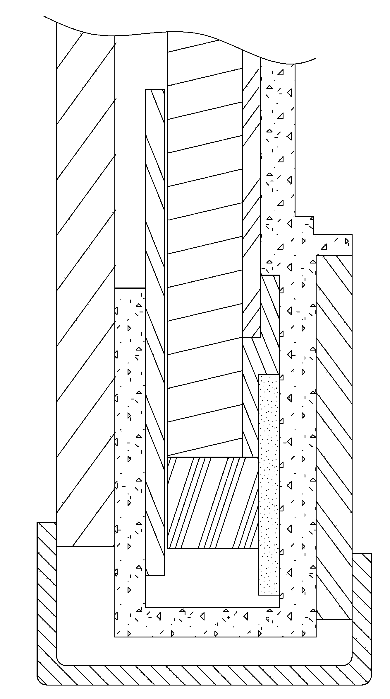
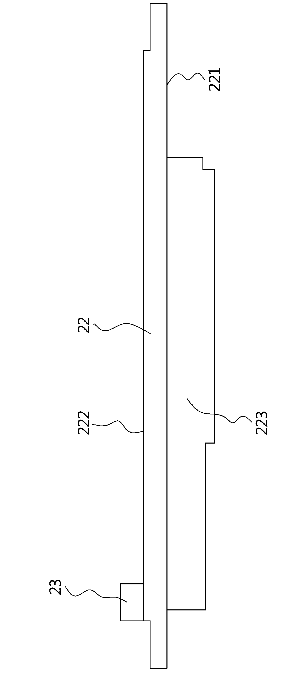
[0052] see figure 2 as shown, figure 2 It is a schematic diagram of an embodiment of the display device of the present invention, as shown in the figure: the display device of this embodiment at least includes a display module 1, a backlight module 2 and a flexible circuit board 3, wherein the backlight module 2 includes at least a frame 21. The driving circuit board 22, the light emitting element 23 and the optical assembly 24, wherein the frame 21 has a housing groove 211, and the above-mentioned driving circuit board 22 is set in t...


PUM


Abstract

The invention provides a backlight module and a display device comprising the same. The display device at least comprises a display module, a backlight module and a flexible circuit board; the backlight module at least comprises a frame, a drive circuit board, light-emitting elements, and an optical component; the display component is disposed on the frame; the flexible circuit board is connected with both the display module and the drive circuit board; in addition, the frame is provided with an accommodating cavity in which the drive circuit board is disposed; one side of the drive circuit board is provided with a drive circuit structure, and the light-emitting elements are disposed on the other side of the drive circuit board. The design that both the light-emitting elements and the drive circuit structure are arranged on the drive circuit board is adopted, the drive circuit board is disposed inside the corresponding accommodating cavity, and accordingly, fewer parts are used and the requirement for decreasing assembly thickness can be met.

Description

technical field [0001] The present invention relates to a display device, and in particular to a backlight module and a display device using the backlight module. Background technique [0002] In order to reflect the light and thin design of current electronic products, the thin structure of the backlight module has always been the focus of research and development by various manufacturers. Please refer to figure 1 Shown is a schematic diagram of a display device designed using a traditional backlight module, from figure 1 It can be seen from the structure that in the current assembly structure, the printed circuit board (PCBA) with the function of driving liquid crystals is folded behind the backlight module and bonded to the frame (Bezel); while the light-emitting element (LED) uses The circuit board and the aforementioned printed circuit board (PCBA) are two independent circuit boards. The existing design uses a flexible circuit board (FPC) to combine the aforementioned ...

Claims


Application Information

Patent Timeline
Patent Type & Authority Applications(China)
IPC IPC(8): F21S8/00F21V17/00F21V17/10F21V23/06G02F1/13357F21Y101/02
Inventor 朱南叡
Owner AU OPTRONICS CORP
Why Eureka
Try Eureka