
Machine tool

A technology of machine tools and gripping parts, applied in the field of machine tools, can solve problems such as mechanical interference, and achieve the effect of preventing mechanical interference

Active Publication Date: 2014-10-01
BROTHER KOGYO KK
View PDF10 Cites 4 Cited by
  • Summary
  • Abstract
  • Description
  • Claims
  • Application Information

AI Technical Summary

Problems solved by technology

When transferring the grip by manual operation, the operator has to transfer the grip adjacent to the grip holding the large-diameter tool to the replacement position, and then perform the tool replacement operation. In this case, there is a problem of mechanical interference.

Method used


Image

  • Machine tool
  • Machine tool
  • Machine tool

Examples


Embodiment Construction

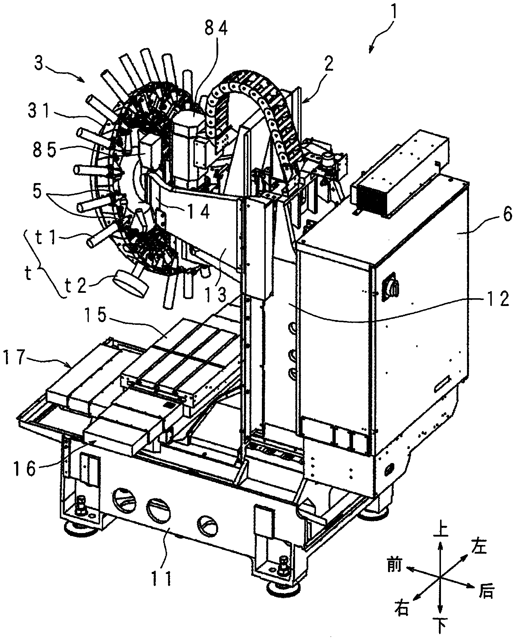
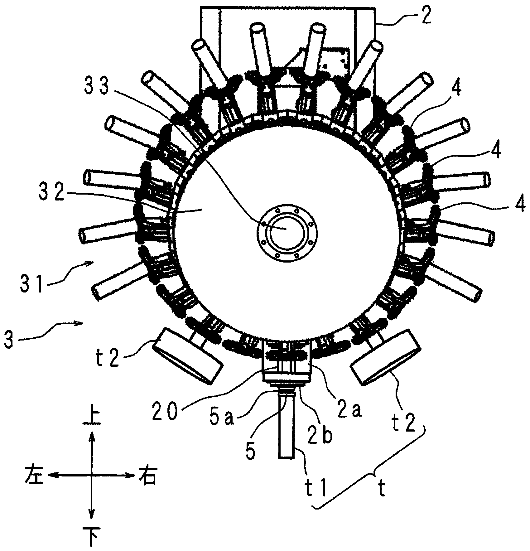
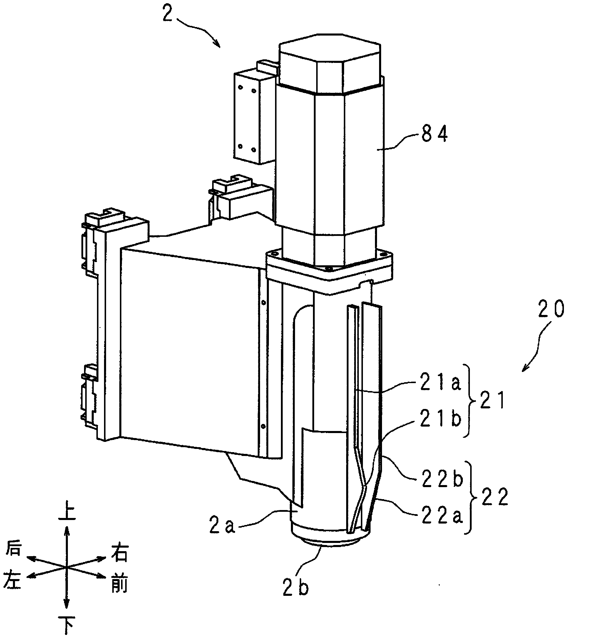
[0029] Hereinafter, a machine tool according to an embodiment of the present invention will be described with reference to the drawings. In the following description, up, down, left, right, front, back, and so forth indicated by arrows in the figure are used. The left-right direction, front-back direction, and up-down direction of the machine tool 1 are the X-axis direction, the Y-axis direction, and the Z-axis direction, respectively. An operator operates the machine tool 1 from the front, and attaches and detaches workpieces. refer to Figure 1 to Figure 6 , the structure of the machine tool 1 will be described.

[0030] The machine tool 1 includes a base 11, a column 12, a spindle head 2 (processing section), a tool changing device 3, a table 15, a control unit 6, and the like. The base 11 is fixed on the ground. The column 12 is erected on the upper rear of the base 11 . The spindle head 2 is movable up and down in the Z-axis direction (up-down direction) along the fr...


PUM


Abstract

The invention relates to a machine tool, and the objective of the machine tool lies in that the mechanical interference is prevented from being generated because of the replacement of a tool when a holding part of a holding tool is forbidden to being located at a replacement position. The machine tool is provided with a warehouse and a control unit. A CPU of the control unit is used for control, thereby enabling a main shaft head to move between a position of a machining area where a workpiece can be machined and the position of an ATC original point where the warehouse can carry the holding part. An EEPROM is corresponding to the holding part, and stores the information whether one of a standard tool (t1) and a big-diameter tool (t2) is held or not. The CPU judges whether the holding part, storing the information of the big-diameter tool (t2), of the EEPROM is adjacent to a holding part located at a position of replacement. When the holding part is adjacent to a holding part located at a position of replacement, the CPU forbids that the main shaft head moves from the position of the ATC original point to the position in the machining zone, thereby preventing the replacement of the tool from generating the mechanical interference.

Description

technical field [0001] The present invention relates to a machine tool which has a magazine in which a plurality of gripping parts for gripping tools is arranged, and which can carry out tool replacement. The magazine can transport the gripping parts. Background technique [0002] Machine tools can perform various processing. A machine tool has a magazine in which a plurality of gripping parts for holding a tool are arranged and the gripping parts can be transported, and a tool taken out of the magazine can be exchanged with a tool attached to a spindle to perform desired machining. [0003] In Japanese Laid-Open Patent Publication No. 0042533 of 1999, a machine tool having a library, a storage unit, and a notification unit is disclosed. A plurality of control parts are arranged in the library. At least one of the plurality of grips holds a tool with a relatively large diameter (hereinafter referred to as a large-diameter tool). If the adjacent grips are not empty, such a ...

Claims


Application Information

Patent Timeline
Patent Type & Authority Applications(China)
IPC IPC(8): B23Q3/157B23Q15/00
CPCB23Q3/157B23Q3/16
Inventor 村上裕
Owner BROTHER KOGYO KK
Learn More