
Microwave signal optical fiber stationary phase transmission system based on microwave phase shifter

A microwave phase shifter and microwave signal technology, applied in the field of microwave photonics, can solve the problems of bandwidth limitation of transmission signals, large phase jitter of transmission signals, and difficulty in real-time compensation of phase jitter, etc. The effect of low maintenance costs

Active Publication Date: 2014-09-24
INST OF SEMICONDUCTORS - CHINESE ACAD OF SCI
View PDF4 Cites 37 Cited by
  • Summary
  • Abstract
  • Description
  • Claims
  • Application Information

AI Technical Summary

Problems solved by technology

At present, the active control method requires multiple mixers, electrical filters and multiple phase-synchronized microwave sources, the system is complex, the cost is high, and it is difficult to operate in practical applications
The other is the passive control method, which obtains the phase difference signal by directly extracting the real-time phase jitter information of the microwave signal modulated on the optical carrier transmitted back and forth in the optical fiber link, and uses the control device to actively compensate the phase of the microwave signal to be transmitted, thereby To stabilize the transmitted microwave signal, the limitation of this method is that the extraction of the phase difference signal mainly relies on the phase-locking technology on the circuit, that is, the phase detector and the loop filter are used to identify the phase jitter information, and the bandwidth of the transmitted signal is limited. In addition, the current devices used for phase compensation mainly include wavelength tunable lasers, adjustable optical / electrical delay lines, fiber stretchers, etc. When the environment changes greatly, the equivalent length of the fiber changes greatly, which causes The phase jitter of the transmission signal is relatively large. Due to the small adjustable range of the above devices, it is difficult to achieve real-time compensation for phase jitter

Method used


Image

  • Microwave signal optical fiber stationary phase transmission system based on microwave phase shifter

Examples


Embodiment Construction

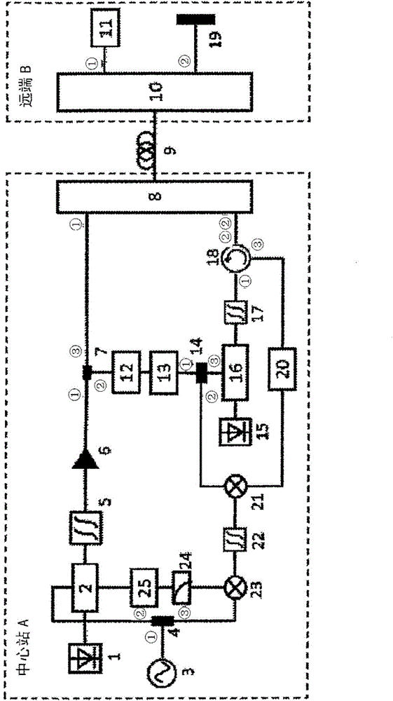
[0036] see figure 1 As shown, the present invention provides a microwave signal optical fiber phase-stable transmission system based on a microwave phase shifter, including: a central station A, a remote B and a single-mode optical fiber 9, and the central station A passes through the single-mode optical fiber 9 Connect with remote B, where:

[0037] Described central station A comprises:

[0038] A semiconductor laser 1, which is used to provide continuous optical carrier;

[0039] A dual-drive Mach-Zehnder modulator 2, the optical input of which is connected to the output of the semiconductor laser 1;

[0040] A microwave signal source 3, the microwave signal source 3 is a vector network analyzer or a microwave signal source, used to generate a local oscillator microwave signal, which is a signal that needs to be transmitted;

[0041] A first power divider 4, its input port 1 is connected with the output end of the microwave signal source 3, and its output port 2 is conne...


PUM


Abstract

The invention discloses a microwave signal optical fiber stationary phase transmission system based on a microwave phase shifter. The system comprises a central station, a far end and a single-mode optical fiber. The central station is connected with the far end through the single-mode optical fiber. The central station is composed of a semiconductor laser device, a dual-drive Mach-Zehnder modulator, a microwave signal source, a first power divider, a first optical filter, an erbium-doped optical fiber amplifier, an optical coupler, a first array waveguide grating, a first photoelectric detector, a frequency eliminator, a second power divider, an optical source, a strength modulator, a second optical filter, an optical circulator, a second photoelectric detector, a first electric mixer, a band-pass filter, a second electric mixer, a low-pass filter and a linear voltage amplification circuit. The far end is composed of a second array waveguide grating, a third photoelectric detector and a Faraday polariscope. According to the invention, the advantage of low building and maintenance cost can be realized; and the phase jitter of microwave signals can be extracted and fed back on a real-time basis.

Description

technical field [0001] The invention relates to a system for phase-stable transmission of microwave signals through optical fibers, specifically a microwave signal optical fiber phase-stable transmission system based on a microwave phase shifter, which belongs to the technical field of microwave photonics. Background technique [0002] In the fields of distributed synthetic aperture radar, deep space exploration, atomic clock distribution, global navigation satellite system and other fields, the phase-stable transmission technology of microwave signals is required. Traditional microwave signal transmission uses coaxial cables for phase-stable transmission, but the cables are large in loss, bulky, and costly, making it difficult to achieve long-distance transmission. Optical fiber is considered to be very suitable for the transmission of microwave signals, especially for long-distance transmission, due to its advantages of low loss, wide bandwidth, anti-electromagnetic interf...

Claims


Application Information

Patent Timeline
IPC IPC(8): H04B10/2575
Inventor 王玮钰李伟孙文惠王文亭刘建国祝宁华
Owner INST OF SEMICONDUCTORS - CHINESE ACAD OF SCI
Learn More