
A multi-frequency multi-point microwave optical fiber phase-stable transmission method based on passive phase correction

A stable phase transmission and phase correction technology, applied in the field of microwave photonics, can solve the problems of slow phase correction speed, single-frequency single-point transmission, etc., achieve fast phase correction, achieve phase correction, and reduce complexity

Active Publication Date: 2018-12-25
SOUTHWEST JIAOTONG UNIV
View PDF3 Cites 0 Cited by
  • Summary
  • Abstract
  • Description
  • Claims
  • Application Information

AI Technical Summary

Problems solved by technology

[0004] In view of the above deficiencies in the prior art, the present invention aims to provide a multi-frequency multi-point microwave optical fiber phase-stabilized transmission method based on passive phase correction, to overcome the disadvantage of slow phase correction speed in traditional phase-stabilized methods and solve the problem of traditional phase-stabilized methods. Defects of single-frequency single-point transmission in phase transmission

Method used


Image

  • A multi-frequency multi-point microwave optical fiber phase-stable transmission method based on passive phase correction
  • A multi-frequency multi-point microwave optical fiber phase-stable transmission method based on passive phase correction
  • A multi-frequency multi-point microwave optical fiber phase-stable transmission method based on passive phase correction

Examples


Embodiment Construction

[0021] The technical scheme of the present invention is described in detail below in conjunction with accompanying drawing:

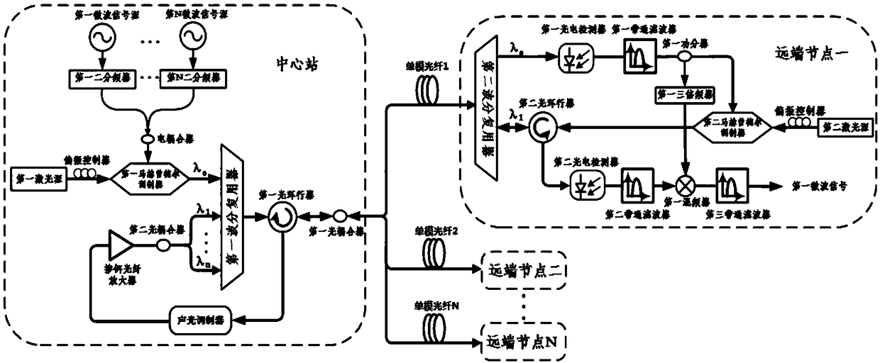
[0022] figure 1 It is a structural schematic diagram of a multi-frequency multi-point microwave optical fiber phase-stable transmission method based on passive phase correction in the present invention, figure 2 It is a system block diagram of a multi-frequency multi-point microwave optical fiber phase-stable transmission method based on passive phase correction in the present invention. Such as figure 2 As shown, the microwave signal optical fiber phase-stable transmission method includes a central station and a plurality of remote nodes, and the central station and a plurality of remote nodes are transmitted through a single-mode optical fiber, wherein:

[0023] The central station includes: microwave signal source 1011, microwave signal source 1012, ..., microwave signal source 101N, laser source 1041, electric coupler 1031, two frequency divider...


PUM


Abstract

The invention discloses a multi-frequency multi-point microwave fiber stable-phase transmission method based on passive phase correction. A central station correspondingly carries out frequency halving on multiple different frequencies of target microwave signals and then coupling the signals into one path which is loaded on an optical signal through modulation for transmission to multiple far-end nodes. For a single far-end node, for example, a far-end node 1, received frequency-halving microwave signal into two paths by a powder divider; one path is subjected to third harmonic generation and the other path is sent back to the central station. At the central station, after other far-end nodes are subjected to the same transmission, obtained microwave signals are coupled with the microwave signal of the far-end node 1. After frequency shift is performed, the obtained signal is transmitted to the far-end node 1 through a wavelength division multiplexer for photoelectric detection and band-pass filtering. An output microwave signal is mixed with a third harmonic generation microwave signal, so a target microwave signal with a stable phase is obtained. According to the invention, time required for phase stabilizing of the microwave is short, quality is high and different frequencies of microwave signals can be transmitted to multiple far-end nodes.

Description

technical field [0001] The invention relates to a microwave signal transmission method, in particular to a multi-frequency multi-point microwave optical fiber phase-stable transmission method based on passive phase correction, and belongs to the technical field of microwave photonics. Background technique [0002] High-quality frequency sources are the core of modern electronic systems, and high-stable frequency standards promote the development of many fields. Microwave photonic technology has the characteristics of small transmission loss, large bandwidth, anti-electromagnetic interference, lightness and flexibility, and easy construction. However, due to the influence of uncontrollable environmental temperature and mechanical stress changes in optical fiber transmission technology, the phase of the signal is random. Drift greatly affects the quality of the microwave signal. This is extremely unfavorable for precise phase feeding in beamforming systems, stable local oscil...

Claims


Application Information

Patent Timeline
Patent Type & Authority Patents(China)
IPC IPC(8): H04B10/2507H04B10/2575H04J14/02
CPCH04B10/2507H04B10/25754H04B10/25759H04J14/0282
Inventor 邹喜华张伟敬罗斌潘炜
Owner SOUTHWEST JIAOTONG UNIV
Learn More