
Difference interference synthetic aperture laser three-dimensional imaging radar transceiving device

A technology of synthetic aperture laser and three-dimensional imaging, which is applied in the direction of measuring devices, instruments, and the use of re-radiation

Active Publication Date: 2014-10-22
SHANGHAI INST OF OPTICS & FINE MECHANICS CHINESE ACAD OF SCI
View PDF3 Cites 23 Cited by
  • Summary
  • Abstract
  • Description
  • Claims
  • Application Information

AI Technical Summary

Problems solved by technology

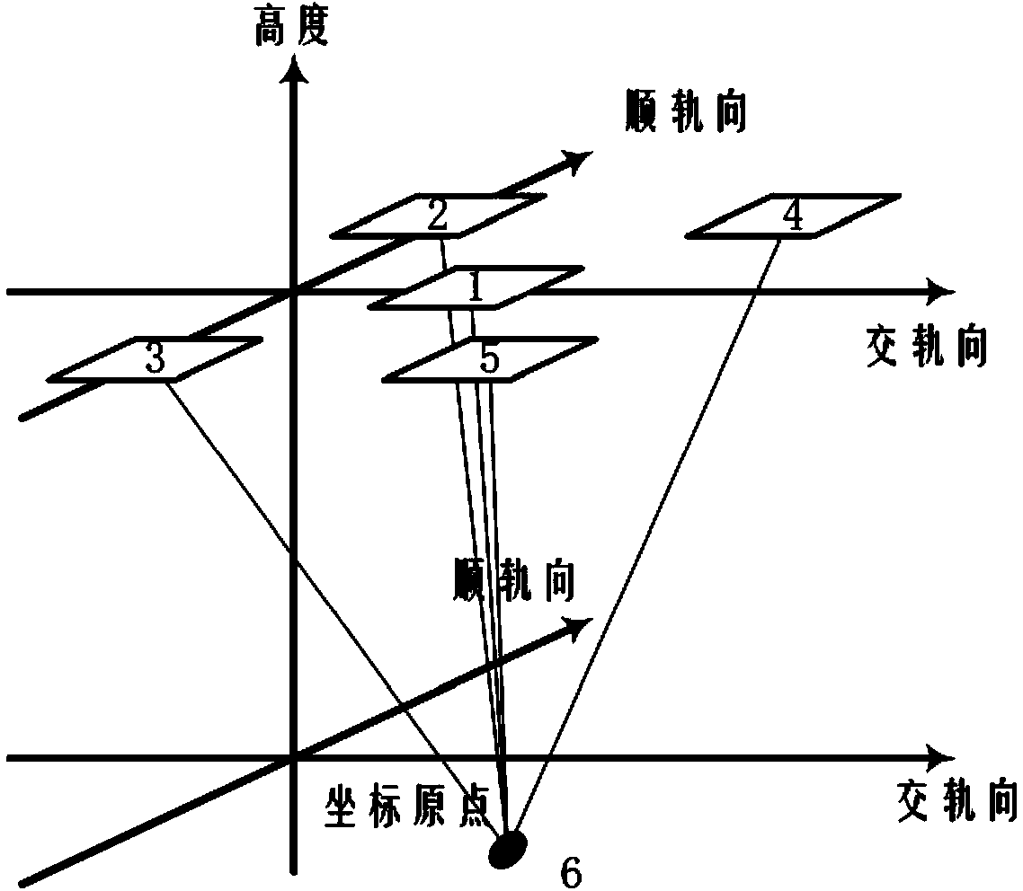
In the prior art [3L.C.Graham,Synthetic interferometer radar for topographic mapping.Proceedings of the IEEE,1974.62(6):p.763‐768.] proposed the interference scheme of microwave synthetic aperture radar, due to synthetic aperture laser imaging The radar uses the 1550nm communication band, which is very sensitive to phase disturbance compared to microwave synthetic aperture radar, so the interference system of microwave synthetic aperture radar is not suitable for synthetic aperture laser imaging radar

Method used


Image

  • Difference interference synthetic aperture laser three-dimensional imaging radar transceiving device
  • Difference interference synthetic aperture laser three-dimensional imaging radar transceiving device
  • Difference interference synthetic aperture laser three-dimensional imaging radar transceiving device

Examples


Embodiment Construction

[0054] The present invention will be further described in detail below in conjunction with the accompanying drawings and examples, but the protection scope of the present invention should not be limited thereby.

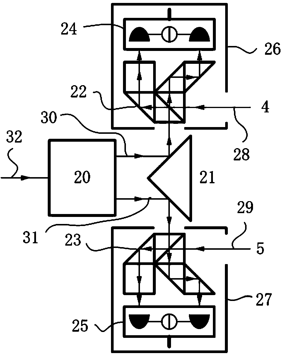
[0055] Such as figure 1 As shown, the present invention is composed of a transmitting antenna 36, ​​a first differential receiving antenna 37, a second differential receiving antenna 38 and a beam splitter;

[0056] Such as figure 2 As shown, the first differential receiving antenna 37 is composed of the first differential receiving antenna beam expander 7, the first differential receiving antenna rectangular prism 8, the first differential receiving antenna bridge 9, the first differential receiving antenna second A bridge 10, a first differential receiving antenna, a first balanced detector 11, a first differential receiving antenna, a second balanced detector 12, a first differential receiving antenna, a first light shield 13, and a first differential receiving ...


PUM


Abstract

A difference interference synthetic aperture laser three-dimensional imaging radar transceiving device is used for transmitting and receiving synthetic aperture laser radar signal light. The difference interference synthetic aperture laser three-dimensional imaging radar transceiving device is formed by a transmitting antenna, a first difference receiving antenna and a second difference receiving antenna. The difference interference synthetic aperture laser three-dimensional imaging radar transceiving device can effectively suppress optical phase errors through difference structures of the receiving antennas and can effectively suppress phase errors caused by radar platform vibration, laser frequency instability and turbulence.

Description

technical field [0001] The invention relates to a synthetic aperture laser three-dimensional imaging radar, in particular to a differential interference synthetic aperture laser three-dimensional imaging radar transceiver. Background technique [0002] Under the premise that the real aperture does not exceed several meters, the synthetic aperture laser imaging radar is the only solution to achieve centimeter-level resolution above 1000km (see prior art 1. Robert L. Lucke, Lee J. Rickard, etc., Synthetic Aperture Ladar (SAL): Fundamental Theory, Design Equations for a Satellite System, and Laboratory Demonstration. Naval Research Laboratory, Dec. 26, 2002.). Ordinary optical remote sensing technology is limited by the size of its real aperture. It is difficult to obtain high resolution without image enhancement technology and prior knowledge during long-distance observation. Wide-bandwidth lasers can obtain extremely high resolution at long distances through synthetic apertu...

Claims


Application Information

Patent Timeline
IPC IPC(8): G01S7/481
CPCG01S7/481G01S17/90
Inventor 孙建锋张宁刘立人周煜孙志伟卢智勇
Owner SHANGHAI INST OF OPTICS & FINE MECHANICS CHINESE ACAD OF SCI
Learn More