
A Current Mode Chaotic Oscillator

A current mode and oscillator technology, applied in power oscillators, electrical components, etc., can solve the problems of chaotic signal bandwidth limitation, voltage mode circuit dynamic range limitation, maximum output voltage limitation, etc., and achieve speed noise immunity, compact structure, The effect of low voltage

Inactive Publication Date: 2016-11-30
TAIYUAN UNIV OF TECH
View PDF3 Cites 0 Cited by
  • Summary
  • Abstract
  • Description
  • Claims
  • Application Information

AI Technical Summary

Problems solved by technology

However, the existing chaotic oscillators based on RC circuits are all based on voltage-mode circuits, and the maximum output voltage is limited by the power supply voltage, especially in analog-digital hybrid integrated circuits.
As the supply voltage decreases, the dynamic range of the voltage mode circuit is more easily limited
In addition, the bandwidth of the chaotic signal generated by the voltage mode circuit is largely limited by the use of operational amplifiers

Method used


Image

  • A Current Mode Chaotic Oscillator
  • A Current Mode Chaotic Oscillator
  • A Current Mode Chaotic Oscillator

Examples


Embodiment Construction

[0025] The implementation of the present invention is illustrated by specific specific examples below, and those skilled in the art can easily understand other effects and characteristics of the present invention through the content disclosed in this specification.

[0026] The structures, sizes and proportions shown in the drawings attached to this specification are only used to match the content disclosed in the specification, for those who are familiar with this technology to read and understand, and are not used to limit the limited conditions that the present invention can be implemented , so it has no technical substantive significance, any modification of structure, change of size and adjustment of proportional relationship should still fall within the scope covered by the technical content disclosed in the present invention. In addition, terms such as "upper", "lower", "left", "right" and "one" quoted in this specification are only for the convenience of description an...


PUM


Abstract

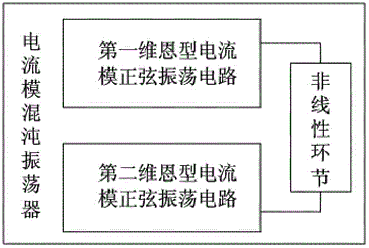
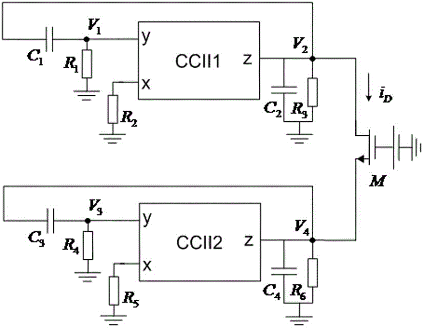
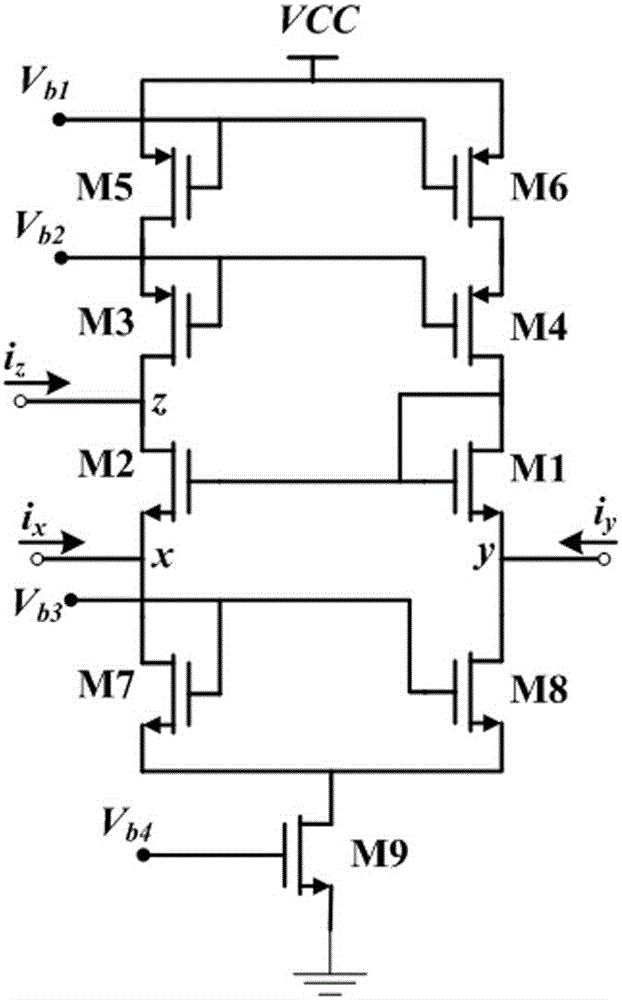
The invention relates to the technical fields of microelectronics and solid electronics, in particular to a current mode chaotic oscillator. The current mode chaotic oscillator comprises a first Wien type current mode sinusoidal oscillation circuit, a second Wien type current mode sinusoidal oscillation circuit and a nonlinear link; the output signal of the first Wien type current mode sinusoidal oscillation circuit is passed through the nonlinear After the link, it is coupled with the output signal of the second Wien type current mode sinusoidal oscillation circuit to obtain a continuous chaotic oscillation signal. The current mode chaotic oscillator of the present invention is suitable for realization on a single integrated circuit chip, and has compact structure, low power consumption and low voltage. Using the current transmitter as an active device enables the chaotic oscillator to have the performance of wide frequency band, high speed and noise immunity, and has high practical value. At the same time, since the circuit design of the present invention has strong symmetry, the chaotic feature of the output signal has high robustness to process changes.

Description

technical field [0001] The invention relates to the technical fields of microelectronics and solid electronics, in particular to a current mode chaotic oscillator. Background technique [0002] The invention relates to the technical fields of microelectronics and solid electronics, in particular to a current mode chaotic oscillator. Background technique [0003] Chaos is a pseudo-random phenomenon generated by a definite nonlinear system, which has initial value sensitivity and broadband characteristics. Because simple nonlinear dynamical systems can produce complex dynamical behaviors, chaos has been widely used in information engineering fields such as information encryption, secure communication and chaotic radar. The chaotic signal source is the premise of the chaotic application, and its circuit realization and the characteristics of the chaotic signal generated are the focus of research and the basis of practical application. [0004] As a chaotic signal source, th...

Claims


Application Information

Patent Timeline
Patent Type & Authority Patents(China)
IPC IPC(8): H03B5/18
Inventor 贾华宇郭燕
Owner TAIYUAN UNIV OF TECH
Learn More