
A line-selecting annular cavity for chemical laser devices

A chemical laser and ring cavity technology, applied in lasers, laser components, phonon exciters, etc., can solve problems such as high threshold, poor beam quality, and large noise, and achieve low threshold, reduce optical loss, and beam quality Good results

Active Publication Date: 2017-07-21
DALIAN INST OF CHEM PHYSICS CHINESE ACAD OF SCI
View PDF4 Cites 0 Cited by
  • Summary
  • Abstract
  • Description
  • Claims
  • Application Information

AI Technical Summary

Problems solved by technology

Moreover, most of the current line-selecting lasers use a standing wave cavity structure, which has high noise, high threshold, and poor beam quality.

Method used


Image

  • A line-selecting annular cavity for chemical laser devices
  • A line-selecting annular cavity for chemical laser devices

Examples


Embodiment Construction

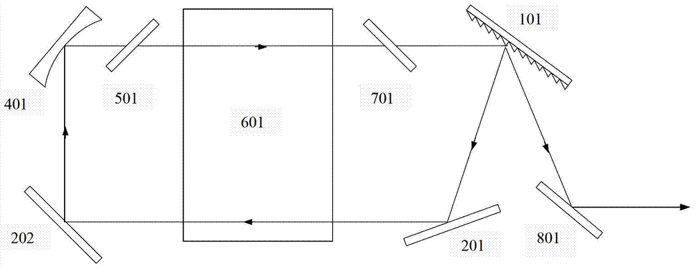
[0032] as attached figure 1 As shown, the structure of the line-selecting four-mirror rectangular cavity used in the chemical laser device of the present invention includes: a gain medium region 601, a Brewster plate I 701, a blazed grating 101, two plane mirrors 201, 202, and a plano-concave mirror 401, Brewster sheet II 501, plane mirror III 801.

[0033] The blazed grating 101 is placed on a motorized turntable, and its diffraction angle is adjusted to the diffraction angle corresponding to the line selection wavelength. When the laser is working, the activated medium in the gain medium region 601 produced by the chemical reaction produces stimulated radiation light of different wavelengths, and these radiation lights pass through the Brewster plate I701 and become linearly polarized light whose vibration direction is parallel to the incident plane. When these linearly polarized lights are incident on the blazed grating 101, the radiated light meeting the first-order diff...


PUM


Abstract

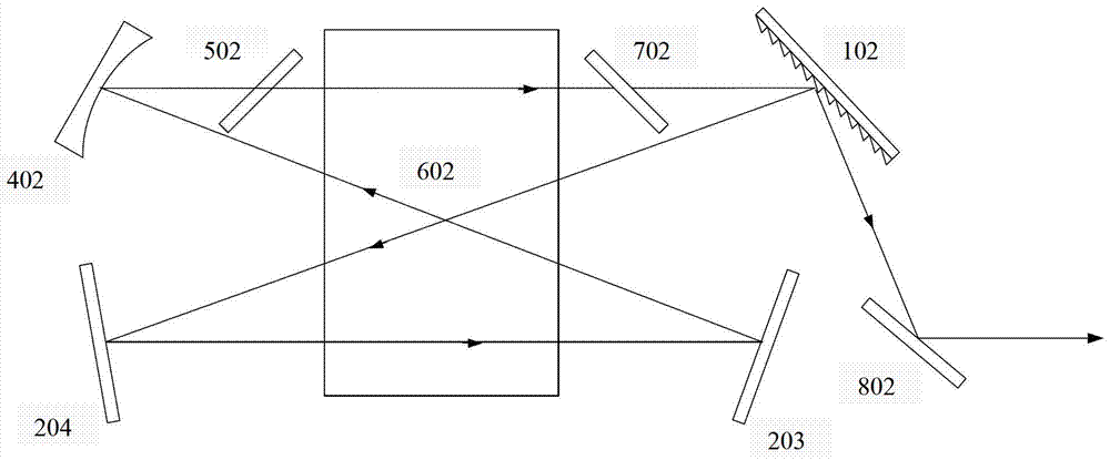
The invention relates to a line-selecting annular cavity for a chemical laser device. The device adopts a stable annular cavity structure, and along the transmission direction of the laser, it is sequentially provided with a blazed grating, a plane reflector, a plane reflector, a plano-concave reflector, and a Burrue. The Steer plate, the active medium area, and the Brewster plate are provided with a flat reflector at the zero-order diffraction output of the blazed grating. The laser device of the present invention uses a fixed diffraction grating to realize the line selection output of the chemical laser by utilizing the first-order diffraction oscillation and the zero-order diffraction output. The resonant cavity of the laser adopts a four-mirror rectangular traveling wave cavity or a four-mirror "8" ring traveling wave cavity structure, which enables the laser to more effectively extract the active particles in the gain medium region and increase the output power of the line-selected laser. With compact structure, high power, good beam quality and high stability, it can be widely used in laser physics, laser chemistry, material processing and other fields.

Description

technical field [0001] The invention belongs to the field of chemical laser devices, and in particular relates to a line selection ring resonant cavity used for chemical laser devices. Background technique [0002] Since the advent of chemical lasers, they have developed rapidly due to their wide application prospects. Chemical lasers have many significant advantages, such as high energy conversion efficiency and output power, and good scalability. They usually work in the mid-infrared band with good atmospheric transmission and rich laser spectral lines. They are the lasers with the highest output power applied so far. Mid-infrared chemical lasers usually operate with multiple lines because the gain coefficients of each spectral line are relatively close. If a certain transition line needs to be selected, a dispersive element needs to be placed in the cavity to suppress the transition of other lines. Because of its good directional diffraction ability, the blazed grating i...

Claims


Application Information

Patent Timeline
Patent Type & Authority Patents(China)
IPC IPC(8): H01S3/083
Inventor 王元虎多丽萍唐书凯于海军汪健曹靖康元福金玉奇
Owner DALIAN INST OF CHEM PHYSICS CHINESE ACAD OF SCI
Learn More