
Method and device for two-photon fluorescence stimulated emission differential super-resolution microscopy

A two-photon fluorescence and stimulated emission technology, applied in the field of super-resolution, can solve the problems of limiting microscope imaging depth and strong scattering effect, and achieve the effects of weakening scattering effect, improving signal-to-noise ratio, and large imaging depth

Inactive Publication Date: 2014-09-24
ZHEJIANG UNIV
View PDF4 Cites 42 Cited by
  • Summary
  • Abstract
  • Description
  • Claims
  • Application Information

AI Technical Summary

Problems solved by technology

The traditional fluorescence optical microscope adopts single-photon excitation method, and uses short-wavelength excitation light to excite fluorescence. The sample has a strong scattering effect on short-wavelength excitation light, and the intensity of excitation light decays exponentially with the increase of depth, thus limiting the imaging depth of the microscope.

Method used


Image

  • Method and device for two-photon fluorescence stimulated emission differential super-resolution microscopy
  • Method and device for two-photon fluorescence stimulated emission differential super-resolution microscopy
  • Method and device for two-photon fluorescence stimulated emission differential super-resolution microscopy

Examples


Embodiment Construction

[0042] The present invention will be described in detail below in conjunction with the embodiments and accompanying drawings, but the present invention is not limited thereto.

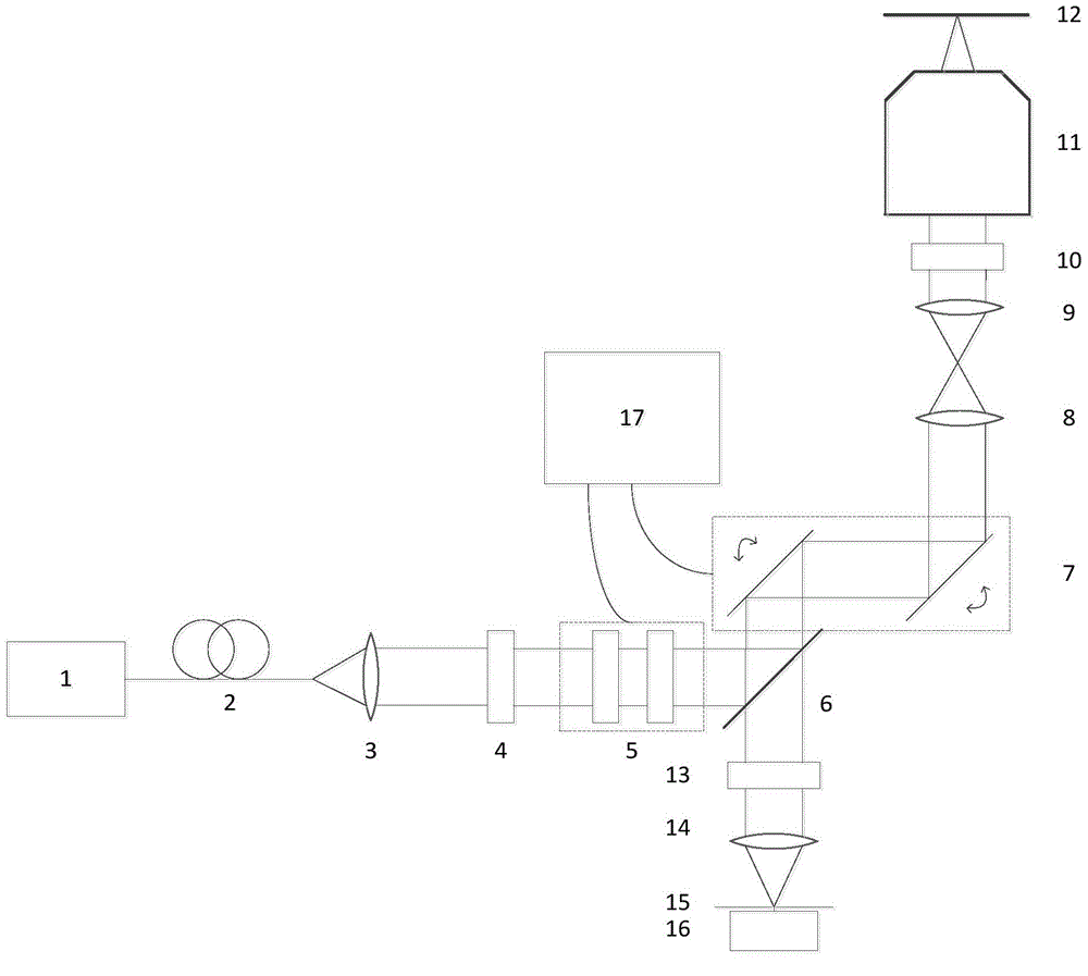
[0043] Such as figure 1 As shown, the fluorescence stimulated emission differential super-resolution microscopy device includes: femtosecond pulsed laser 1, single-mode fiber 2, collimator lens 3, polarizer 4, liquid crystal polarization converter 5, dichroic mirror 6, scanning Galvanometer system 7, scanning lens 8, scene 9, 1 / 4 wave plate 10, microscope objective lens 11, sample stage 12, optical filter 13, focusing lens 14, pinhole 15, detector 16, controller 17.

[0044] Single-mode optical fiber 2, collimator lens 3, polarizer 4, liquid crystal polarization converter 5, dichroic mirror 6 are located on the optical axis of the outgoing beam of femtosecond pulse laser 1 in sequence, and the light transmission axis of polarizer 4 Parallel to the vertical direction, the scanning galvanometer system 7...


PUM


Abstract

The invention discloses a method for two-photon fluorescence stimulated emission differential super-resolution microscopy. The method includes the steps that (1) after being collimated, pulsed laser beams are converted into linear polarized light and polarization modulation is conducted on the linear polarized light, so that radial polarized light is obtained; (2) the radial polarized light is converted into circular polarized light and projected onto a sample to be tested, two-photon stimulated emission is conducted, fluorescence is collected, and therefore first signal light intensity I1 is obtained; (3) polarization modulation is conducted on the linear polarized light obtained in the step (1) and the linear polarized light is converted into tangential polarized light; (4) the tangential polarized light is converted into circular polarized light and projected onto the sample to be tested, two-photon stimulated emission is conducted, fluorescence is collected, and therefore second signal light intensity I2 is obtained; (5) effective signal light intensity I is calculated according to a formula I=I1-gammaI2 , so that super-resolution imaging is achieved. The invention further discloses a device for two-photon fluorescence stimulated emission differential super-resolution microscopy. The device is simple, free of light division, low in light power, capable of weakening the photobleaching effect, higher in resolution and larger in imaging depth.

Description

technical field [0001] The invention relates to the field of super-resolution, in particular to a two-photon fluorescence stimulated emission differential super-resolution microscopy method and device capable of exceeding the diffraction limit in the far field and realizing super-resolution. Background technique [0002] Due to the existence of the optical diffraction limit, the traditional far-field optical microscopy method has a limit to the resolution that can be achieved. This limit is determined by Abbe's diffraction limit theory. After the beam is focused by the microscope objective lens, a blurred spot is formed on the focal plane. The resolution of an optical microscope is defined as the minimum distance between two spots of equal brightness that can be distinguished. Therefore, the size of the spot determines the limit resolution of the microscope. The size of the spot is represented by full width at half maximum (FWHM: Full Width at HalfMaximum) as where λ is t...

Claims


Application Information

Patent Timeline
IPC IPC(8): G02B21/00
Inventor 匡翠方荣子豪刘旭
Owner ZHEJIANG UNIV
Learn More