Signal amplifier circuit of electromagnetic flowmeter

A signal amplification circuit and electromagnetic flowmeter technology, which is applied to amplifiers with semiconductor devices/discharge tubes, amplifiers, improved amplifiers to reduce temperature/power supply voltage changes, etc., can solve the problem of high input impedance of operational amplifiers, reduced input impedance, Deterioration of insulation properties, etc.

Active Publication Date: 2017-09-01
YAMATAKE HONEYWELL CO LTD
View PDF5 Cites 0 Cited by
  • Summary
  • Abstract
  • Description
  • Claims
  • Application Information

AI Technical Summary

Problems solved by technology

[0006] In addition, the input impedance of the FET-input operational amplifier is very high, and the input bias current is also very small, but it is easily affected by noise, etc. generated by peripheral circuits.
In addition, if the insulation properties of the substrate deteriorate due to the influence of surrounding humidity or the adhesion of foreign matter, the input impedance will decrease.

Method used


Image

  • Signal amplifier circuit of electromagnetic flowmeter
  • Signal amplifier circuit of electromagnetic flowmeter
  • Signal amplifier circuit of electromagnetic flowmeter

Examples


Embodiment Construction

[0058] Next, embodiments of the present invention will be described with reference to the drawings.

[0059] [First Embodiment]

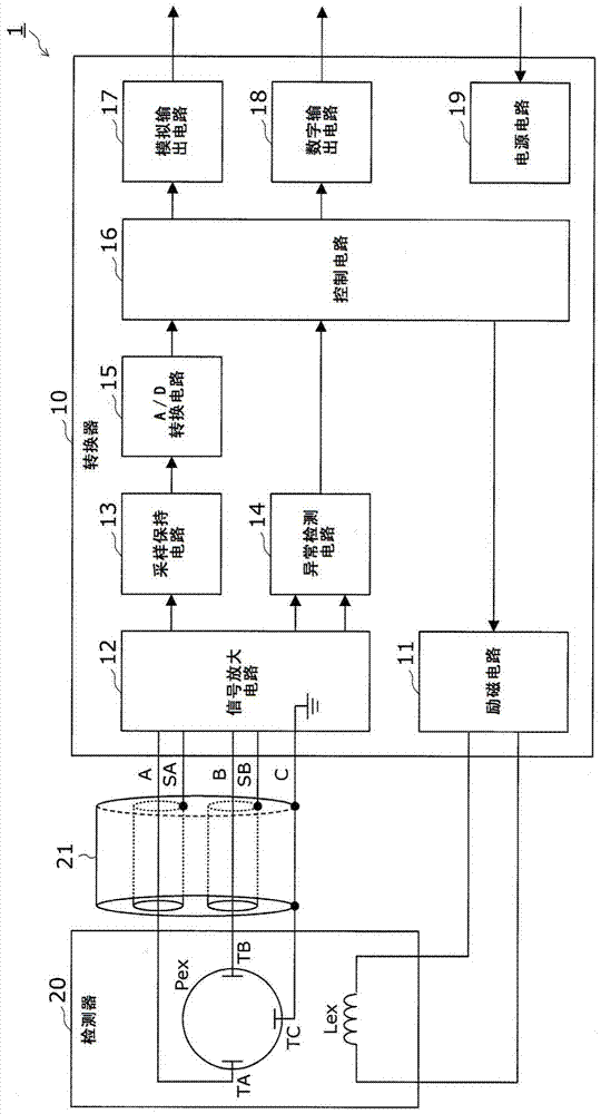
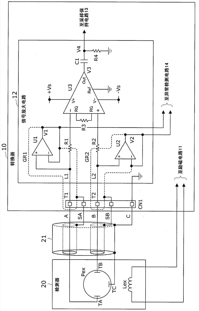
[0060] First, refer to figure 1 as well as figure 2 , the signal amplifying circuit 12 of the electromagnetic flowmeter 1 according to the first embodiment of the present invention will be described. figure 1 It is a block diagram showing the configuration of the electromagnetic flowmeter according to the first embodiment. figure 2 It is a circuit diagram showing the signal amplifier circuit according to the first embodiment.

[0061] This electromagnetic flowmeter 1 includes a converter 10 and a detector 20, and has a function of measuring the flow rate of a conductive fluid.

[0062] The detector 20 is provided with a pipe Pex through which the fluid to be measured for the flow rate flows, and an excitation coil Lex for exciting the fluid in the Pex.

[0063] In the converter 10, an excitation circuit 11, a signal amplification circuit 12...


PUM


Abstract

The present invention provides a signal amplifying circuit of an electromagnetic flowmeter, which can avoid deterioration of CMRR in a differential amplifying circuit caused by a coupling capacitor and delay in recovering from an abnormal input. The flow signal input between the flow signal input terminals (T1, T2) of the connector (CN1) is input to one and the other of the input terminals of the instrument amplifier U3 through the resistance element (R1, R2) and differentially amplified, The amplified output signal (V3) is output to the sample and hold circuit (13) through the coupling capacitor (C1). In addition, the flow signal input to the flow signal input terminal (T1, T2) of the connector (CN1) is buffered by the buffer amplifier (U1, U2), and the output signal (V1, V2) is output to the abnormality detection circuit (14 ). At this time, guard the wiring patterns (L1, L2) connecting the flow signal input terminals (T1, T2) and the non-inverting input terminals of the buffer amplifiers (U1, U2) with guard ring patterns (GR1, GR2).

Description

technical field [0001] The invention relates to an electromagnetic flowmeter, in particular to a signal amplifying circuit technology for amplifying electromotive force obtained from a detector. Background technique [0002] In general, in an electromagnetic flowmeter that measures the flow rate of a conductive fluid, an excitation current that alternates in polarity is supplied to the excitation coil to detect the electromotive force generated between a pair of detection electrodes, and a signal amplification circuit is used to detect the electromotive force generated between a pair of detection electrodes. Differential amplification, sampling the obtained flow signal and performing signal processing, thereby measuring the flow rate of the fluid flowing in the pipe, wherein the excitation coil is arranged so that the magnetic field generation direction and the flow direction of the fluid flowing in the pipe Perpendicularly, the pair of detection electrodes are arranged in t...

Claims


Application Information

Patent Timeline
Patent Type & Authority Patents(China)
IPC IPC(8): G01F1/60
CPCG01F1/60H03F1/30H03F3/45071
Inventor 百濑修光武一郎松永晋辅井上阳牛山昌秀
Owner YAMATAKE HONEYWELL CO LTD
Why Eureka
Try Eureka