
Nozzle Ring With Non-uniformly Distributed Airfoils And Uniform Throat Area

A nozzle ring and root technology, which is applied to the components of the pumping device for elastic fluids, engine functions, liquid fuel engines, etc., can solve the problems of reduced thermal efficiency of the turbine stage, uneven flow, etc. Reduced production and maintenance costs, high thermal efficiency

Inactive Publication Date: 2014-09-24
ABB TURBO SYST
View PDF7 Cites 3 Cited by
  • Summary
  • Abstract
  • Description
  • Claims
  • Application Information

AI Technical Summary

Problems solved by technology

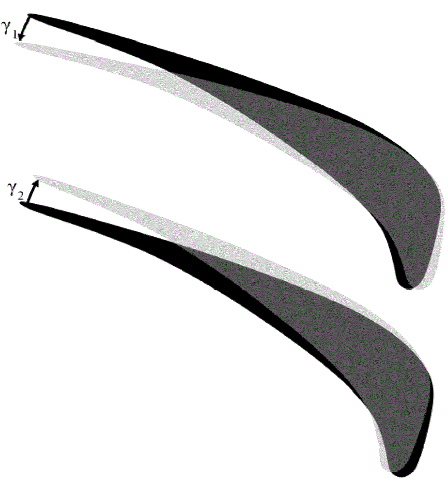
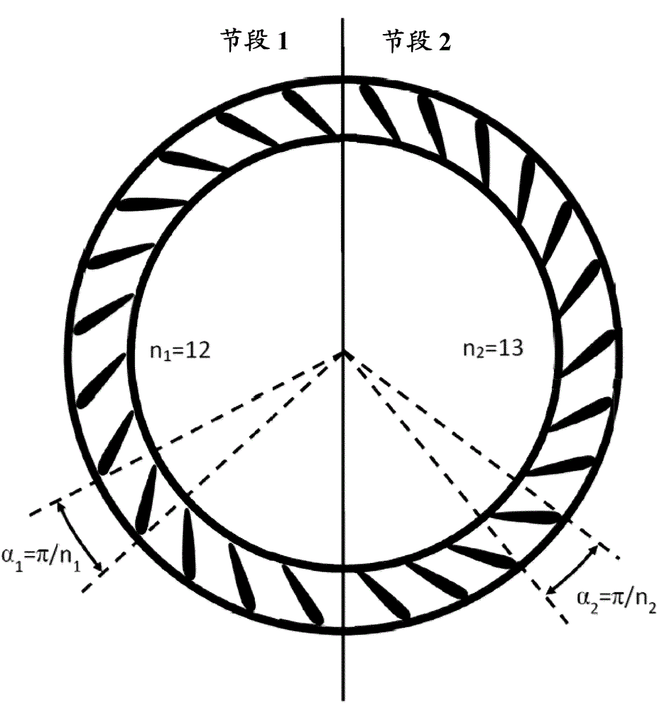
Due to the inhomogeneity of the flow, the rotor is excited in the first mode shape and the thermodynamic efficiency of the turbine stage is reduced compared to a stage with a nozzle ring consisting of uniformly distributed vanes

Method used


Image

  • Nozzle Ring With Non-uniformly Distributed Airfoils And Uniform Throat Area
  • Nozzle Ring With Non-uniformly Distributed Airfoils And Uniform Throat Area
  • Nozzle Ring With Non-uniformly Distributed Airfoils And Uniform Throat Area

Examples


Embodiment Construction

[0030] Each vane of the nozzle ring comprises a root portion conventionally fixedly attached to the inner support ring, a tip portion conventionally fixedly attached to the outer support ring, a leading edge facing the upstream direction, a trailing edge facing the downstream direction , and oppositely oriented suction (or convex) and pressure (or concave) sides that extend from the leading edge to the trailing edge, and between the root and the tip.

[0031] Adjacent vanes define converging passages between them to direct combustion gases between the vanes, through a throat, and downstream from the throat to a conventional turbine rotor stage (not shown). ).

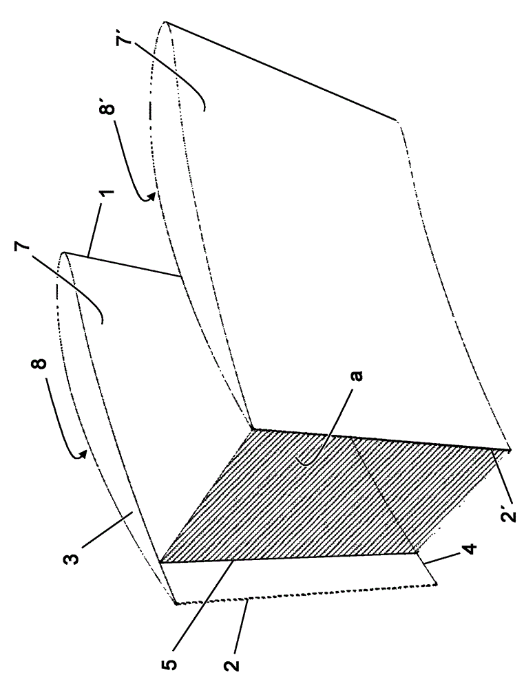
[0032] as stated above and Figure 4 Each vane has a leading edge 1 and a trailing edge 2 as shown in . Each vane has a root 4 immovably attached to one support ring, and a tip 3 immovably attached to the other support ring. The pressure side 7 , 7 ′ and the suction side 8 , 8 ′ extend from the leading edge 1 to the t...


PUM


Abstract

For the segmented nozzle ring introduced herewith, the throat area between neighboring vanes is the same for each segment which is achieved by rotation (i.e., opening or closing of the throat area) of the individual vane compounds belonging to the different segments. The resulting uniform throat area leads to a uniform exit flow angle of the nozzle and a uniform inlet flow angle of the rotor. Based on that, high-cycle fatigue excitations of the rotor caused by the non-uniform flow are eliminated, the thermodynamic efficiency of the turbine stage can be improved, and the nozzle ring must not be arranged in a fixed position relative to the gas inlet casing.

Description

technical field [0001] The present invention relates generally to exhaust gas turbines for turbochargers of internal combustion engines, and more particularly to nozzle rings for directing the flow of exhaust gas in such gas turbines. Background technique [0002] A conventional exhaust gas turbine with a fixed turbine geometry for a turbocharger of an internal combustion engine comprises a turbine nozzle for directing the exhaust gas to a plurality of rotor blades. The turbine nozzle includes a plurality of circumferentially spaced stator vanes fixedly coupled at their roots and tips to radially inner and radially outer annular support rings. In the case of a radial flow turbine or a mixed flow turbine, the stator vanes of the nozzle ring are fixed at their roots and tips to an annular support ring arranged adjacent to each other on each opposite side of the flow channel. [0003] like Figure 4 As shown in , each nozzle vane has an airfoil cross-section with a leading edg...

Claims


Application Information

Patent Timeline
Patent Type & Authority Applications(China)
IPC IPC(8): F01D9/04
CPCF02B37/22F01D9/041F05D2260/961F04D29/666F05D2220/40F04D29/328F04D29/327
Inventor S.M.森恩
Owner ABB TURBO SYST
Learn More