Auger supporting device
A support device and auger technology, applied in packaging, pivot connection, etc., can solve the problems of affecting the service life of the sand conveying auger, affecting production efficiency, workload and difficulty
- Summary
- Abstract
- Description
- Claims
- Application Information
AI Technical Summary
Problems solved by technology
Method used
Image
Examples
Embodiment Construction
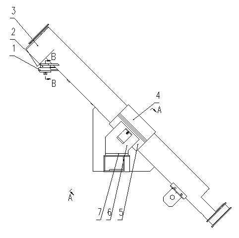
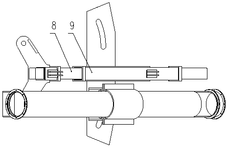
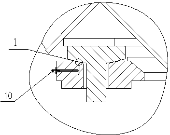
[0015] Referring to the accompanying drawings, an auger support device includes a concave spherical support plate 1, a convex spherical pin shaft 2, an auger shell 3, an upper guide sleeve 4, a lower guide sleeve 5, a support frame body 6, a backing plate 7, and a movable rectangular Tube 8, fixed rectangular tube 9, oil cup 10, lock nut 11, mandrel 12, nylon roller 13, U-shaped bracket 14, convex spherical surface pin 2 welded on auger shell 3, concave spherical surface supporting plate 1 welded On the movable rectangular tube 8, the convex spherical surface pin shaft 2 is inserted into the pin hole of the concave spherical surface supporting plate 1, the movable rectangular tube 8 is set in the fixed rectangular tube 9, and the upper guide sleeve 4 and the lower guide sleeve 5 are bolted together. Together, the lower guide sleeve 5 is welded to the support frame body 6, and the backing plate 7 is placed under the support frame body 6; the convex spherical surface pin shaft 2 ...
PUM
 Abstract
Description
Claims
Application Information
 - R&D
- Intellectual Property
- Life Sciences
- Materials
- Tech Scout
- Unparalleled Data Quality
- Higher Quality Content
- 60% Fewer Hallucinations
Browse by: Latest US Patents, China's latest patents, Technical Efficacy Thesaurus, Application Domain, Technology Topic, Popular Technical Reports.
© 2025 PatSnap. All rights reserved.Legal|Privacy policy|Modern Slavery Act Transparency Statement|Sitemap|About US| Contact US: help@patsnap.com


