Electric fuse structure and method of forming the same

An electric fuse and fuse technology, applied in circuits, electrical components, electric solid devices, etc., can solve the problems of large integrated circuit area and high cost, and achieve the effect of saving chip area, easy to generate heat, and easy to fuse

Active Publication Date: 2016-08-31
SEMICON MFG INT (SHANGHAI) CORP
View PDF7 Cites 0 Cited by
  • Summary
  • Abstract
  • Description
  • Claims
  • Application Information

AI Technical Summary

Problems solved by technology

However, the existing electric fuse is not easy to blow, and occupies a large area of ​​the integrated circuit, and the cost is high

Method used


Image

  • Electric fuse structure and method of forming the same
  • Electric fuse structure and method of forming the same
  • Electric fuse structure and method of forming the same

Examples


Embodiment Construction

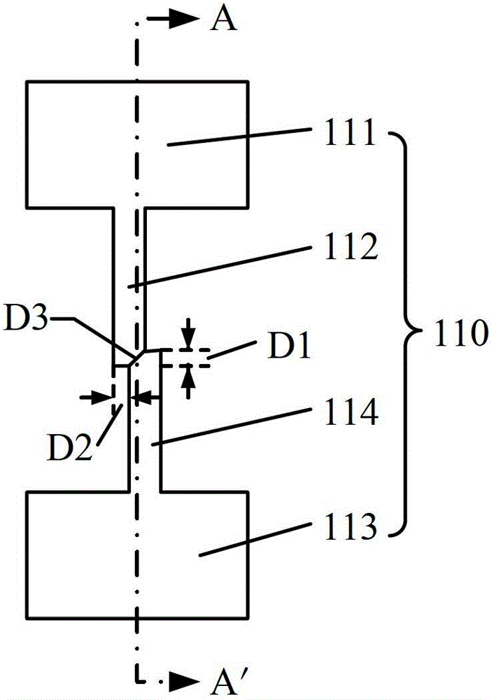
[0033] Since the electric fuse requires a large fusing current to blow the electric fuse, the program power supply of the electric fuse needs a programming transistor with a large area to generate a large fusing current, which increases the size and cost of the integrated circuit. And because electromigration causes electric fuse disconnection, it is often because a large amount of metal atoms in the electric fuse accumulate, so that holes are formed in the electric fuse, which leads to the electric fuse disconnection, and when the length of the electric fuse in the prior art is long It is easy to cause a large number of metal atoms to accumulate to form voids. Therefore, the length of the existing electric fuse formed by metal is often longer, and the area and cost of the integrated circuit will also be increased.

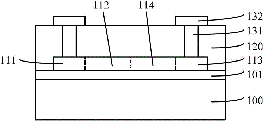
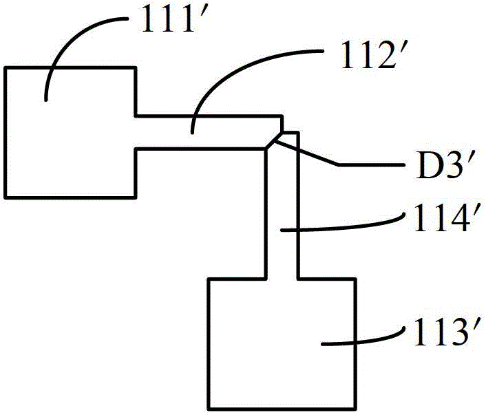
[0034]For this reason, the inventor has proposed an electric fuse structure and a method for forming the same after research. The distance between the two interse...


PUM


Abstract

An electric fuse structure and a forming method thereof, the electric fuse structure comprising: a substrate, an insulating layer positioned on the surface of the substrate; an electric fuse positioned on the surface of the insulating layer, the electric fuse including a first electrode , a strip-shaped first fuse connected to the first electrode, a second electrode and a strip-shaped second fuse connected to the second electrode, the first fuse and the second fuse are connected and connected There is a dislocation at the position, and the distance between the two intersections of the edge of the first fuse and the edge of the second fuse at the dislocation is less than or equal to the width of the first fuse and less than or equal to the width of the second fuse; A metal interconnection structure on the surface of the first electrode and the second electrode. Since the distance between the two intersection points at the dislocation is the smallest, the resistance of the electric fuse at the dislocation becomes larger, so that more heat is generated at the dislocation, and it is easier to fuse, so that the fusing current does not need to be too large, and the length of the electric fuse It does not need to be too long, thereby saving the chip area.

Description

technical field [0001] The invention relates to the technical field of semiconductors, in particular to an electric fuse structure and a forming method thereof. Background technique [0002] With the continuous reduction of feature size, semiconductor devices are more and more susceptible to impurities or defects in the silicon substrate, and the failure of a single diode or MOS transistor often leads to the failure of the entire integrated circuit chip. In order to solve the above problems and improve the yield, some redundant circuits are often formed in the integrated circuit chip. When the manufacturing process is completed and it is found that some devices cannot work normally, the fuse can be used to electrically isolate the failed circuit from other circuit modules, and the redundant circuit can be used to replace the original failed circuit. Especially in the manufacturing process of memory, due to the large number of memory cells, it is inevitable that some memory ...

Claims


Application Information

Patent Timeline
Patent Type & Authority Patents(China)
IPC IPC(8): H01L23/525H01L21/768
Inventor 廖淼
Owner SEMICON MFG INT (SHANGHAI) CORP
Why Eureka
Try Eureka