
Electronic percussion instrument

一种打击乐器、电子的技术,应用在打击乐器、电声乐器、乐器等方向,能够解决撞击传感器检测精度变差等问题,达到改善振动阻尼效果的效果

Active Publication Date: 2014-09-17
YAMAHA CORP
View PDF6 Cites 3 Cited by
  • Summary
  • Abstract
  • Description
  • Claims
  • Application Information

AI Technical Summary

Problems solved by technology

In the absence of the aforementioned damping buffer, electronic percussion instruments experience continuous vibrations on the drumhead for a long time, which in turn degrades the detection accuracy of the impact sensor

Method used


Image

  • Electronic percussion instrument
  • Electronic percussion instrument
  • Electronic percussion instrument

Examples


Embodiment Construction

[0042] The present invention is described in further detail by way of example with reference to the accompanying drawings.

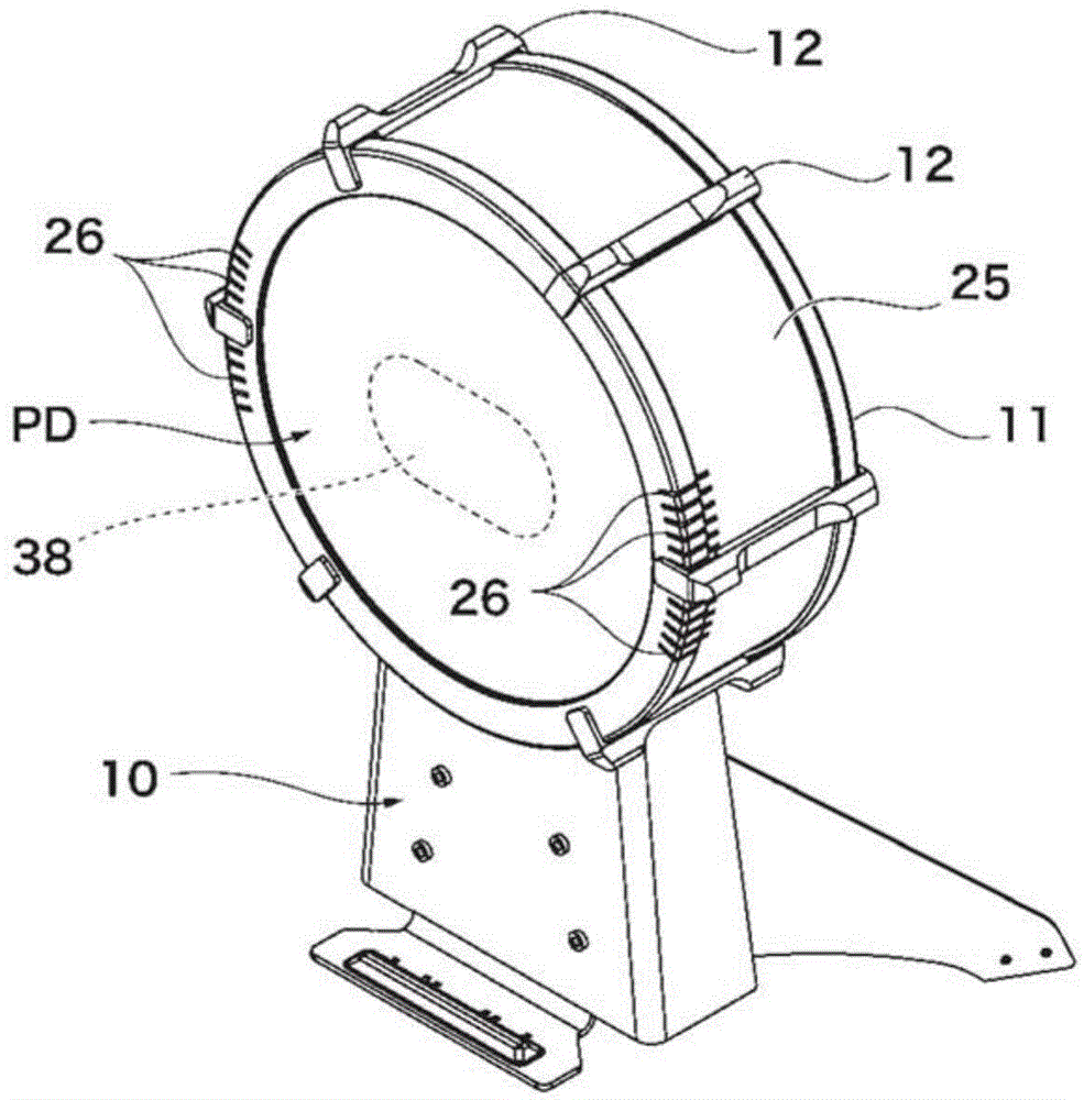
[0043] Figure 1A is a perspective view showing the front side of an electronic percussion instrument according to a preferred embodiment of the present invention, and Figure 1B is a perspective view showing the rear side of the electronic percussion instrument excluding the cover. Figure 2A is a front view of an electronic percussion instrument, while Figure 2B It is a side view of an electronic percussion instrument.

[0044] The electronic percussion instrument of the present embodiment is used as an electronic bass drum in which the main body is used as a kick pad supported by the stand 10 . A foot pedal device (not shown) is additionally attached to the front side of the electronic percussion instrument near a player (for example, a drummer) who plays the electronic percussion instrument. For convenience, the four directions (that is, up, down...


PUM


Abstract

An electronic percussion instrument includes a head, a frame, and an impact sensor, and a plate serving as a vibration-damping member. The back of the head is divided into a main area (e.g. a main strike area) and an auxiliary area. The plate is ring-shaped sheet, made of a harder material (e.g. a metal) than the head, with an elongated hole and attached to the head to encompass or sandwich the main strike area of the head, thus demonstrating a vibration-damping effect. When the main strike area of the head is being struck with a beater, a vibration is caused to occur in the head and detected by the impact sensor to produce an electric signal which is used to generate an electronic musical sound while the vibration-damping member suppresses vibration being transmitted through the head due to an impact of the beater on the head.

Description

technical field [0001] The present invention relates to an electronic percussion instrument including an impact sensor that converts the vibration of a drum head struck by a drum hammer into an electric signal so as to generate an electronic musical sound. Background technique [0002] Conventionally known electronic percussion instruments are designed to produce electronic musical sounds based on electrical signals output from impact sensors that detect vibrations of drumheads struck by drum hammers. Patent Document 1 (PLT 1) discloses an electronic percussion instrument as an electronic bass drum having a circular head made of an elastic material, the periphery of which is joined to a frame. The impact sensor is attached to the back of the striking area corresponding to the center of the drumhead via a central buffer, and the outer periphery is surrounded by an annular damping buffer. Vibration waves are generated when the striking area of ​​the drumhead is struck by the ...

Claims


Application Information

Patent Timeline
Patent Type & Authority Applications(China)
IPC IPC(8): G10H3/12
CPCG10D13/02G10D13/024G10H3/146G10D13/26G10H1/32G10H2220/525G10H2230/291
Inventor 金山惠美佐藤正男
Owner YAMAHA CORP
Learn More