Multi-beam parabolic antenna multi-channel dynamic packet switching method

A technology of parabolic antenna and packet switching, which is applied in the radio wave measurement system, radio wave reflection/reradiation, utilization of reradiation, etc., can solve the problems of high escape probability, increased complexity of intermediate frequency signal processing and hardware resource scale of receiving equipment, The thermal design of the center body is difficult to meet the requirements and other problems, so as to achieve the effect of reducing the escape probability

Active Publication Date: 2016-10-05
10TH RES INST OF CETC
View PDF7 Cites 0 Cited by
  • Summary
  • Abstract
  • Description
  • Claims
  • Application Information

AI Technical Summary

Problems solved by technology

[0004] If 252 sub-beam feeds correspond to 252 receiving channels, there will be the following problems: 1. The structural layout and installation of the antenna center body is difficult; 2. The thermal design of the center body is difficult to meet the requirements; 3. Increase the back-end IF signal processing Complexity and receiving device hardware resource scale
[0006] 1) The target signal is always in the channel corresponding to the packet edge coverage, and the static packet switching cannot support the accurate angle estimation algorithm of adjacent channel weighting processing
Therefore, the angle estimation error is large, resulting in a relatively low probability of system guidance
[0007] 2) In the process of packet switching, it cannot be guaranteed that the target signal is always within the coverage of the current switching packet beam
Therefore, the escape probability is high and the detection probability of the system is relatively low

Method used


Image

  • Multi-beam parabolic antenna multi-channel dynamic packet switching method
  • Multi-beam parabolic antenna multi-channel dynamic packet switching method
  • Multi-beam parabolic antenna multi-channel dynamic packet switching method

Examples


Embodiment Construction

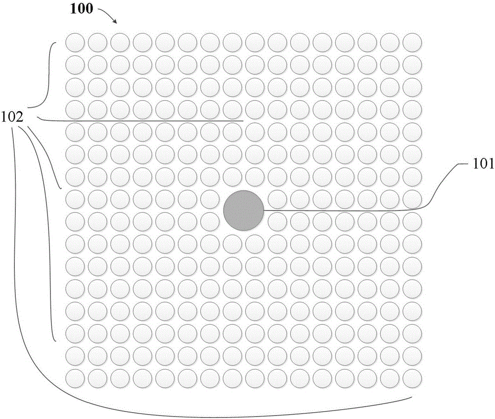
[0024] refer to figure 1 . The multi-beam parabolic antenna beam channel array 100 includes a main beam channel 101 corresponding to the main beam feed source in the center of the multi-beam parabolic antenna and sub-beam channels 102 arranged around the main beam channel 101 . The total number of sub-beam channels 102 is 252 in total, and sub-beam feeds n=16×16-4=252, where “4” occupies 4 sub-beam feed positions for the main beam feed, that is, a multi-beam parabolic antenna The airspace that the beam can cover is 3°×3°

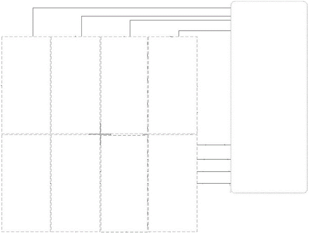
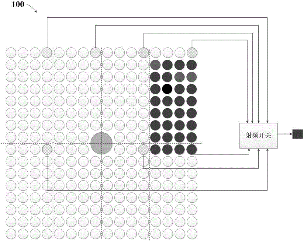
[0025] exist figure 2 In the given multi-beam parabolic antenna beam channel array matrix 100, the entire sub-beam is evenly divided into where n is the number of sub-beam feeds, p is the number of rectangular areas, and m is the number of beam channels. The sub-beam feed takes the main feed as the phase center, and divides the entire rectangular sub-beam equally into and the channels in the same position in the p rectangular areas are connected to t...


PUM


Abstract

The invention provides a method for multichannel dynamic grouping switching of multi-beam parabolic antennas and aims to provide a method for quickly finishing high-dynamic target incoming signal detection, performing continuous reliable guidance and saving device resources. The technical scheme is that n-path signals output by a multi-beam offset-focus feed source field are connected to m radio frequency switching switches through radio frequency cables, a connecting method is that channels having the same position in p rectangular areas integrally averagely divided are connected to the same radio frequency switching switch; at a target signal admission stage, the radio frequency switching switches are sequentially switched to scan the p rectangular areas, target signal detection is finished; after detecting target admission, the radio frequency switching switches determine whether to perform dynamic grouping switching operation with whether target signals fall into the grouping edge serving as the grouping switching judging basis; and after the target signals enter the main beam coverage area and a main tracking receiver performs locking, the radio frequency switching switches are switched to enable auxiliary beams corresponding to a current communicating channel to surround a main beam.

Description

technical field [0001] The invention relates to a method for guiding high dynamic target angles in the form of a multi-beam parabolic antenna through multi-channel dynamic group switching in a near-space high-speed aircraft measurement and control system. Background technique [0002] Near-space hypersonic vehicles have the characteristics of low orbit (40km-70km) and large motion dynamics (moving speed up to Mach 22, angular velocity 6° / s). When the aircraft re-enters the atmosphere, the plasma sheath effect will be generated on the surface of the aircraft, that is, the "black barrier" phenomenon of the radio communication link. In order to overcome the influence of "black barrier", in the system design of measurement and control communication equipment, the Ka frequency band is generally considered. However, as the working frequency increases, the beam width will be greatly reduced for the same caliber antenna. If the system uses an antenna with a caliber of 3.8m, the 3d...

Claims


Application Information

Patent Timeline
Patent Type & Authority Patents(China)
IPC IPC(8): G01S13/68
CPCG01S7/034G01S13/68
Inventor 黄展胡建平刘胜利
Owner 10TH RES INST OF CETC
Why Eureka
Try Eureka