
A steam boiler comprising a radiation element

A technology of radiant elements and steam boilers, applied in the direction of steam superheating, boiler water pipes, steam generation, etc., which can solve the problems of large complexity and cost, and increased wear of superheater tubes

Inactive Publication Date: 2014-09-10
SANDVIK INTELLECTUAL PROPERTY AB
View PDF9 Cites 0 Cited by
  • Summary
  • Abstract
  • Description
  • Claims
  • Application Information

AI Technical Summary

Problems solved by technology

However, this approach involves greater boiler complexity and cost, and increases wear and tear on the superheater tubes and other parts in the boiler interior

Method used


Image

  • A steam boiler comprising a radiation element
  • A steam boiler comprising a radiation element
  • A steam boiler comprising a radiation element

Examples


example

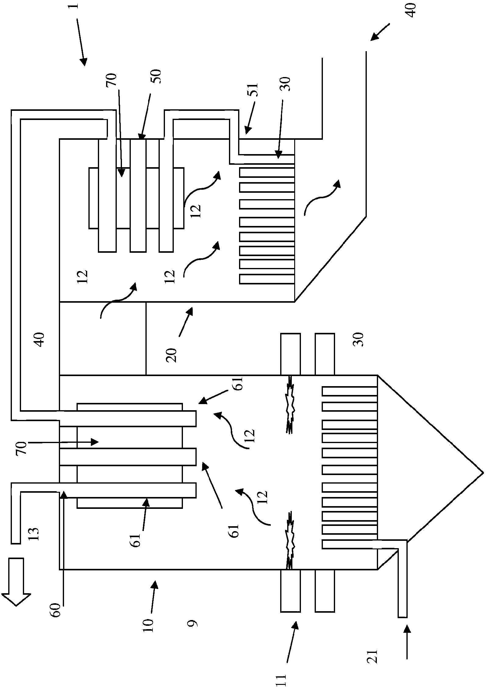
[0107] In the following, the heating effect of the radiation element of the present invention in a steam boiler will be shown through a calculation example. In the examples, temperature and heat transfer calculations have been made based on empirical data from conventional boiler designs. The smoke absorption and emission coefficients are assumed to be equal, and all surfaces are assumed to have emission and absorption coefficients of 0.8 and also have the same convective heat transfer. For the calculation, primary radiation, primary and secondary reflections and absorption in the gas volume have been considered.

[0108] Calculations showing the heat absorbed in the superheater arrangement in an oil fired compact boiler. Calculations were performed for the inventive superheater arrangement with radiating elements and for a conventional superheater arrangement without radiating elements.

[0109] Figure 6 A side view showing a conventional superheater tube arrangement. Th...


PUM


Abstract

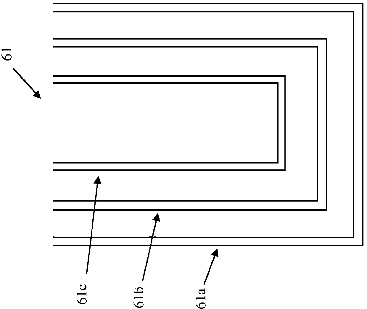
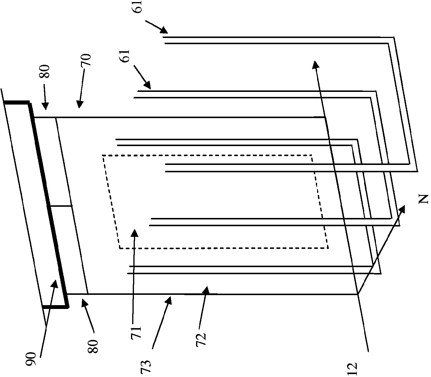
A steam boiler (1) comprising at least one water and / or steam conveying element (30, 60) that is heated by the hot flue gases in the boiler characterized in that the steam boiler (1) comprises at least one radiation element (70) wherein; said radiation element (70) is an un-cooled element; said radiation element (70) is arranged in the flow of hot flue gases (12) such that it is convectively heated by the flue gases; said radiation element (70) is located at a pre-determined distance from said at least one water and / or steam conveying element (30, 60) wherein said predetermined distance is adapted such that the flow of hot flue gases between the radiation element and the water and / or steam conveying element is unhindered, and such that the water and / or steam conveying element is heated by heat radiation from said radiation element.

Description

technical field [0001] The invention relates to a steam boiler according to the preamble of claim 1 . Background technique [0002] Steam boiler power plants have water and / or steam delivery elements, such as steam tubes in the boiler wall, and usually also superheaters, to deliver the saturated steam produced in the boiler to dry superheated steam of Effective for power generation. [0003] The general principle of operation of boilers producing hot water or steam is to produce hot flue gases by burning fossil fuels or renewable fuels to produce hot water or steam which, in the case of power plants, is converted into electricity. The hot gas transfers thermal energy through a heat exchanger to hot water or pressurized steam, which can be used in industrial processes for heating homes and industries, or in power boilers to generate electricity. In the latter case, the final stage of heat transfer is usually done in a superheater, usually consisting of tube bundles arranged...

Claims


Application Information

Patent Timeline
Patent Type & Authority Applications(China)
IPC IPC(8): F22B37/10
CPCF22B37/10F22G1/06F22G7/14
Inventor 保·荣松
Owner SANDVIK INTELLECTUAL PROPERTY AB
Learn More