
Soil strength detection sensor

A sensor and strength technology, applied in the field of sensors, can solve the problems of rough classification of tunnel surrounding rock, easy damage, inconvenient operation, etc., and achieve the effect of speeding up the detection operation speed, uniform expansion or contraction, and convenient detection operation.

Active Publication Date: 2014-09-10
广东省水利电力勘测设计研究院有限公司
View PDF6 Cites 0 Cited by
  • Summary
  • Abstract
  • Description
  • Claims
  • Application Information

AI Technical Summary

Problems solved by technology

[0002] At present, the sensors used in the known strength detection of complex rock and soil around the tunnel are not accurate, easy to damage, and not easy to carry. At the same time, the installation conditions of the device are relatively high. The stress-sensitive components (such as the stress-sensing device composed of strain gauges) Large size, it is difficult to test the strength of weak interlayers, fault fracture zones, and crack-intensive areas in surrounding rocks, and the classification of tunnel surrounding rocks is relatively rough, and it is inconvenient to operate when using, which seriously affects the working face and work efficiency of side pressure tests

Method used


Image

  • Soil strength detection sensor
  • Soil strength detection sensor
  • Soil strength detection sensor

Examples


Embodiment Construction

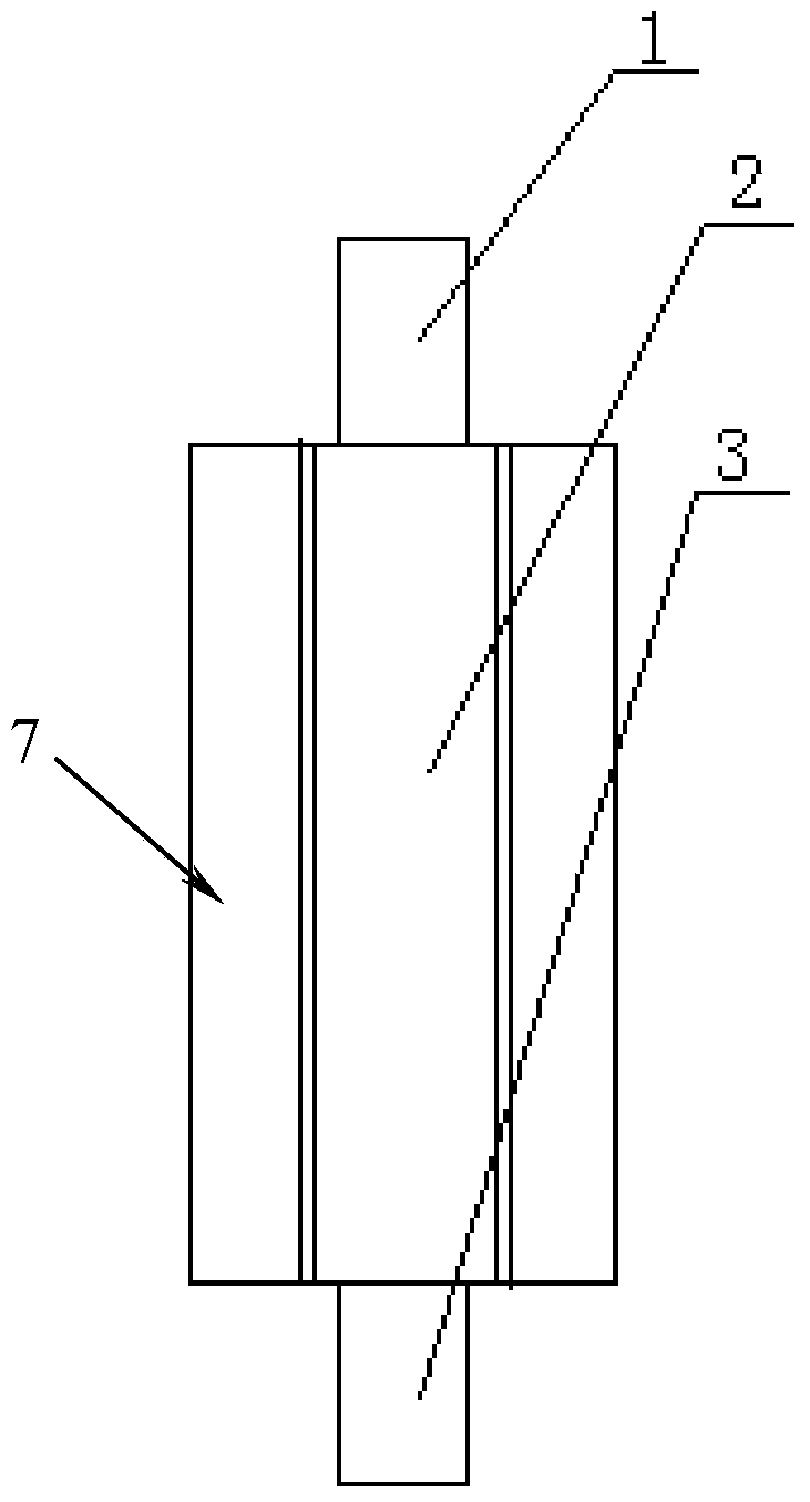
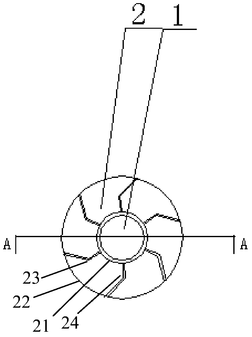
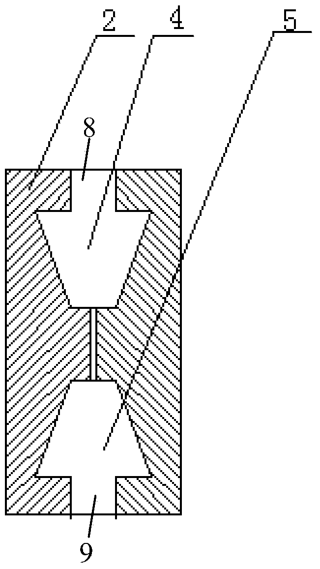
[0019] like Figure 1~4 The shown soil strength detection sensor includes a first push rod 1, a second push rod 3 and a plurality of sensing strips 2 made of pressure-sensitive materials, each sensing strip 2 surrounds a cylindrical expansion column 7, The top surface of the expansion column 7 is provided with a first sliding hole 8 downwards, and the expansion column 7 at the lower end of the first sliding hole 8 is provided with a first movable chamber 4, which is conical; the bottom surface of the expansion column 7 A second sliding hole 9 is opened upward, and a second movable chamber 5 is provided in the expansion column 7 at the top of the second sliding hole 9, and the second movable chamber 5 is conical; one end of the first push rod 1 is inserted into the first movable chamber 4, and is provided with the first conical head 6 that slides with the chamber wall of the first movable chamber 4; A second conical head (not shown) for sliding engagement with the wall.

[00...


PUM


Abstract

The invention discloses a soil strength detection sensor comprising a first push rod, a second push rod and multiple sensor bars. The sensor bars are made of pressure sensitive materials and surround to form a cylindrical expansion column, a first sliding hole is formed in the top face of the expansion column downwardly, a first moving cavity which is conical is arranged in the expansion column at the lower end of the first sliding hole, a second sliding hole is formed in the bottom surface of the expansion column upwardly, a second moving cavity which is conical is arranged in the expansion column at the top end of the second sliding hole, one end of the first push rod is inserted into the first moving cavity and is provided with a first cone head in sliding fit with the wall of the first moving cavity, and one end of the second push rod is inserted into the second moving cavity and provided with a second cone head in sliding fit with the wall of the second moving cavity. The soil strength detection sensor is small in size, portable, convenient for detection and simple to operate.

Description

technical field [0001] The invention relates to a sensor, in particular to a soil strength detection sensor. Background technique [0002] At present, the sensors used in the known strength detection of complex rock and soil around the tunnel are not accurate, easy to damage, and not easy to carry. At the same time, the installation conditions of the device are relatively high. The stress-sensitive components (such as the stress-sensing device composed of strain gauges) The volume is large, it is difficult to test the strength of weak interlayers, fault fracture zones, and crack-intensive areas in the surrounding rock, and the classification of the tunnel surrounding rock is relatively rough, and it is inconvenient to operate during use, which seriously affects the working face and work efficiency of the side pressure test. Contents of the invention [0003] In order to overcome the deficiencies of the prior art, the purpose of the present invention is to provide a soil st...

Claims


Application Information

Patent Timeline
Patent Type & Authority Applications(China)
IPC IPC(8): E02D1/00G01N3/00
Inventor 程小勇龚惠军陈训源
Owner 广东省水利电力勘测设计研究院有限公司
Learn More