
Wind-powered self-cleaning system for stagnant water lake

A self-cleaning, stagnant water technology, applied in the field of water cleaning systems, can solve the problems of difficult professional operation requirements, high input costs, and high consumption costs, and achieve the effects of meeting the needs of water, being environmentally friendly, and improving water quality

Inactive Publication Date: 2014-09-10
HOHAI UNIV
View PDF5 Cites 1 Cited by
  • Summary
  • Abstract
  • Description
  • Claims
  • Application Information

AI Technical Summary

Problems solved by technology

For the ecological method, which is to add bacteria, animals and plants in the lake water and control their quantity to achieve ecological balance, this method has high input costs and difficult requirements for professional operations.
For the physical method, the operation is easier to master, that is, to use the device to divert and exchange water to achieve the purpose of lake water self-circulation, but the traditional method of using electric pump device to pump water and using tap water to replenish water is costly.

Method used


Image

  • Wind-powered self-cleaning system for stagnant water lake
  • Wind-powered self-cleaning system for stagnant water lake
  • Wind-powered self-cleaning system for stagnant water lake

Examples


Embodiment Construction

[0016] The present invention will be further explained below in conjunction with the accompanying drawings and specific embodiments. It should be understood that the following specific embodiments are only used to illustrate the present invention but not to limit the scope of the present invention.

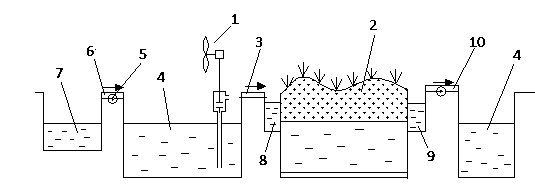
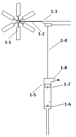
[0017] figure 1 It is a structural schematic diagram of the present invention, as can be seen from the figure, the bottom of the wind lifter 1 is inserted into the low place of the backwater lake 4, the impeller 1-1 and the piston pump 1-5 are located above the lake surface, and the water outlet 1-8 of the wind lifter 1 Connected to the water delivery pipe 3, the water delivery pipe 3 sends the water in the backwater lake 4 to the wetland treatment system 2, and the water in the backwater lake 4 is naturally purified in the wetland treatment system 2, and then discharged into the backwater lake 4 again, followed by Carry out to ensure that the water in the stagnant lake 4 can mai...


PUM


Abstract

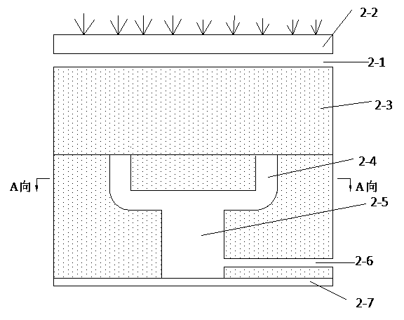
The invention discloses a wind-powered self-cleaning system for a stagnant water lake. The wind-powered self-cleaning system comprises a wind-powered lifter arranged at the lowest position in a stagnant water lake and a wetland processing system, wherein the wind-powered lifter is connected with the wetland processing system through a water conveying pipe; the wetland processing system comprises a water distribution pipe; a lawn is laid on the water distribution pipe; a soil layer is laid below the water distribution pipe; a plurality of branched water collecting wells are distributed below the soil layer; a plurality of adjacent branch water collecting wells are converged to a master water collecting well; a water discharging pipe for leading out water is arranged on the sidewall of the master water collecting well; an impervious barrier is arranged at the bottom of the master water collecting well; the water discharging pipe is connected back to the stagnant water lake; the water conveying pipe is connected to the water distribution pipe; and the stagnant water lake is connected to a rainwater accumulating tank through a lifting pump and a water pipe. In the wind-powered self-cleaning system disclosed by the invention, the wind-powered lifter is used for sending water from the stagnant water lake to the wetland processing system and then water enters the water distribution pipe so as to meet the growth requirement of the lawn; the water permeates into the soil layer and is purified by the soil, then is collected in the master water collecting well, led out through the water discharging pipe and finally discharged to the stagnant water lake, thus the water quality is purified, the cost is low and the effect is good.

Description

technical field [0001] The invention relates to a wind energy self-cleaning system for a stagnant lake, which is a water cleaning system which uses wind energy as a driving force to purify water through soil and lawns. Background technique [0002] In the construction of urban parks and campuses, artificial lakes and landscape pools are constantly emerging, and landscape water is slowly integrated into people's lives. The self-purification ability is weak, and once it is polluted, it will deteriorate rapidly and it is not easy to recover. To fundamentally guarantee the water quality of landscape water, certain water source protection and water treatment measures must be taken. Water treatment technology is a technology that treats water quality through physical, chemical and biological methods to meet the needs of people's lives, industrial production and the environment. At present, there are many ways to purify lake water, the more representative ones are physical and ch...

Claims


Application Information

Patent Timeline
Patent Type & Authority Applications(China)
IPC IPC(8): C02F3/32C02F3/34
CPCY02W10/33
Inventor 叶芬赵振宙陈景茹李涛许波峰黄娟郑源赵振宁
Owner HOHAI UNIV
Learn More