
Paper shredding cutting tool and machining device and method thereof

A processing method and cutting tool technology, applied in the direction of grain processing, etc., can solve the problems of difficult helical arrangement of cutting edges, difficult to achieve firmness and strength, etc., to achieve simple processing methods, good usability and firmness, easy The effect of promoting the application

Inactive Publication Date: 2014-09-10
AURORA OFFICE EQUIP
View PDF10 Cites 2 Cited by
  • Summary
  • Abstract
  • Description
  • Claims
  • Application Information

AI Technical Summary

Problems solved by technology

[0008] The invention provides a paper shredding cutter and its processing equipment and processing method, in order to solve the problem that in the prior art, it is difficult to make the cutter and the cutter shaft fit closely by directly assembling the bump and the through groove, and it is difficult to achieve firmness in use. Degree and strength, and the defect that it is difficult to achieve the helical arrangement of the tool tip

Method used


Image

  • Paper shredding cutting tool and machining device and method thereof
  • Paper shredding cutting tool and machining device and method thereof
  • Paper shredding cutting tool and machining device and method thereof

Examples


Embodiment 1

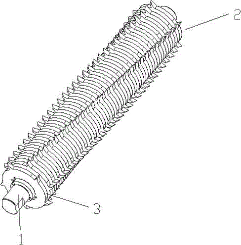
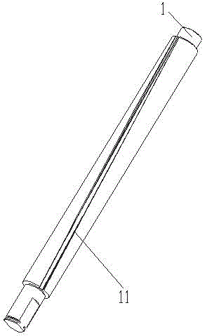
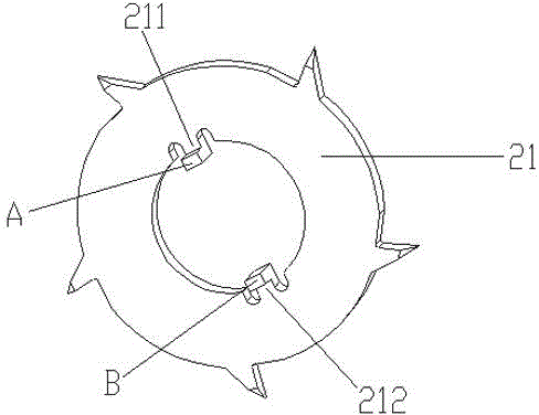
[0054] see figure 1 , a paper shredding cutter provided in this embodiment includes a cutter shaft 1 and a matching blade set 2; the blade set 2 includes a certain number of blades 21, and all the blades 21 are threaded on the cutter shaft 1 in a certain order, see figure 2 , the cutter shaft 1 is cylindrical, with two symmetrical spiral grooves on its surface (it can be seen that the spiral groove on one side is 11); see image 3 , the inner hole circumference of each blade 21 in the blade set 2 is provided with two protruding positioning ribs corresponding to the two spiral grooves of the cutter shaft 1, respectively recorded as 211, 212, and each positioning rib includes a height The protrusions that are beyond the plane of the blade body and can fit into the spiral groove of the cutter shaft 1 are respectively marked as A and B. These protrusions can be flatly assembled in the spiral groove of the cutter shaft 1 and passed It is firmly fixed in it after riveting. Prefe...

Embodiment 2

[0063] see Figure 9 , a paper shredding cutter provided in this embodiment, including a cutter shaft 1 and its matching blade set 2 and blade spacer ring 3, the cutter shaft 1 has two symmetrical spiral grooves on the surface (it can be seen that the spiral groove on one side is 11) Cylindrical cutter shaft for , see figure 2 , the inner holes of all the blades of the blade group 2 are circular, and the inner holes of all the blade spacer rings 3 are also circular, and the circumference of the inner holes of the blade spacer rings 3 are correspondingly provided with two spiral grooves that can be loaded into the cutter shaft. The protruding positioning ribs are recorded as 31 and 32 respectively. Preferably, the two protruding positioning ribs also protrude toward the outer circumference of the blade spacer ring 3 at the same time, see Figure 10 , the positioning ribs 31, 32 can be assembled in the corresponding spiral grooves of the cutter shaft 1, and firmly fixed in the...


PUM


Abstract

The invention discloses a paper shredding cutting tool and a machining method thereof. A cutter shaft of the paper shredding cutting tool is provided with a spiral groove; blades or blade spacer rings are provided with protruding blocks; the protruding blocks are firmly fixed in the spiral groove in a riveting pressure machining mode and accordingly a paper shredding machine can be good in usage and firmness. The invention also discloses a machining device which is suitable for the machining method, particularly a riveting pressure module. Optimally, the riveting pressure module is arranged into two semi-circular rings and the inner lateral sides of the semi-circular rings are provided with protruded riveting pressure points to be beneficial to assembly of the riveting pressure module, riveting pressure implementation and detachment of the riveting pressure module. Accordingly, the process that the blades are fixed on the cutter shaft is greatly improved.

Description

technical field [0001] The invention relates to the field of paper shredders, in particular to paper shredder cutters, in particular to a paper shredder cutter and its processing equipment and processing method. Background technique [0002] Paper shredders are commonly used machines for destroying confidential documents in offices and homes. The paper shredder mainly uses groups of shredding blades fixed on two parallel and relatively rotating knife shafts to squeeze waste paper when the two knife shafts rotate at the same time, thereby using the shredding blades on the knife shafts to The waste paper is cut into thin paper strips or shreds, so the quality of the shredding cutter (composed of the cutter shaft and the shredding blade) and the improvement of the production method are particularly important. [0003] At present, shredder cutters and their processing technology are usually divided into the following three categories: [0004] 1. Fixing method of the blade spa...

Claims


Application Information

Patent Timeline
Patent Type & Authority Applications(China)
IPC IPC(8): B21D39/00B02C18/18
Inventor 陈光龙左永康
Owner AURORA OFFICE EQUIP
Learn More