
Novel chip mounting head and chip mounting machine

A patch head, a new type of technology, applied in the direction of assembling printed circuits with electrical components, can solve problems such as inconvenience, and achieve the effects of improving work efficiency, simplifying structure, and reducing moving mass

Active Publication Date: 2014-09-03
BEIJING TORCH CO LTD
View PDF6 Cites 3 Cited by
  • Summary
  • Abstract
  • Description
  • Claims
  • Application Information

AI Technical Summary

Problems solved by technology

[0004] This shows that the above-mentioned existing patch head obviously still has inconvenience and defects in structure and use, and needs to be further improved urgently

Method used


Image

  • Novel chip mounting head and chip mounting machine

Examples


Embodiment Construction

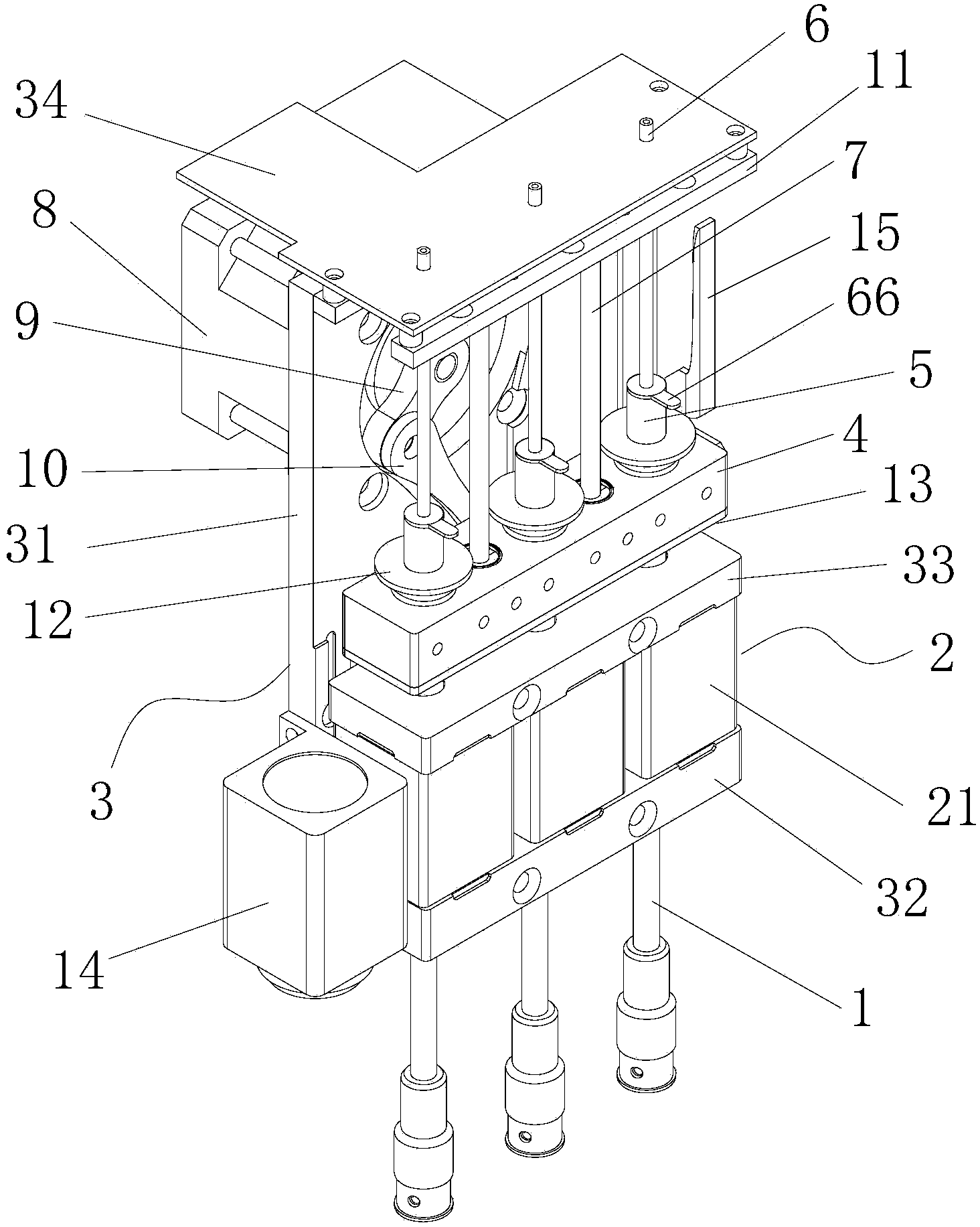
[0023] In order to further explain the technical means and effects of the present invention to achieve the intended purpose of the invention, the specific implementation, structure, characteristics and effects of the new patch head proposed according to the present invention will be described below in conjunction with the accompanying drawings and preferred embodiments. Details are as follows. In the following description, different "one embodiment" or "embodiment" do not necessarily refer to the same embodiment. Furthermore, the particular features, structures, or characteristics of one or more embodiments may be combined in any suitable manner.

[0024] figure 1 It is a structural schematic diagram of an embodiment of the new patch head of the present invention. Such as figure 1 As shown, a new patch head includes a vertically arranged suction rod 1 and a horizontal rotation motor 2 that drives the suction rod 1 to rotate in the horizontal direction. The horizontal rotati...


PUM


Abstract

The invention discloses a novel chip mounting head and a chip mounting machine. The novel chip mounting head comprises a vertical suction rod and a horizontal rotating motor for driving the suction rod to rotate in the horizontal direction. The horizontal rotating motor comprises a motor body and an output shaft, wherein the suction rod serves as the output shaft of the horizontal rotating motor, the suction rod can slide relative to the motor body in the vertical direction. The novel chip mounting head is simple in structure, high in speed and high in efficiency, and movable units are small in quality.

Description

technical field [0001] The invention relates to the technical field of electronic placement, in particular to a novel placement head and placement machine. Background technique [0002] As the pillar equipment in the field of electronic placement, the placement machine has the advantages of fast placement speed, high placement accuracy, stable and reliable placement quality, which has completely changed the characteristics of labor-intensive enterprises in the placement field and greatly improved Production efficiency, liberating the labor force, is an indispensable equipment for the modern SMT placement industry. [0003] The placement head is an important part of the placement machine, which plays an important role in the work efficiency and accuracy of the placement machine. In order to improve the efficiency and accuracy of the placement machine, reducing the volume and weight of the placement head is the direction pursued by those skilled in the art. The existing patc...

Claims


Application Information

Patent Timeline
Patent Type & Authority Applications(China)
IPC IPC(8): H05K3/30
Inventor 赵永先张延忠
Owner BEIJING TORCH CO LTD
Learn More