
Testing method for pulse modulated signals

A technology of pulse modulation signal and test method, applied in the direction of pulse shaping, pulse description, etc., can solve the problems that it is difficult to obtain accurate synchronous trigger signal in time, only know the distribution of pulse or time slot, and cannot analyze or distinguish, etc. , to achieve the effect of reducing data rate, realizing low cost, accurate positioning and selection

Active Publication Date: 2014-09-03
CHINA ELECTRONIS TECH INSTR CO LTD
View PDF5 Cites 10 Cited by
  • Summary
  • Abstract
  • Description
  • Claims
  • Application Information

AI Technical Summary

Problems solved by technology

[0003] Disadvantages of the prior art: it is necessary to input a trigger signal from the outside of the signal analyzer, and at the same time, the trigger signal must accurately correspond to the time of the signal to be analyzed. For the signal generated by the user himself, this trigger signal can be obtained. It is difficult to obtain such time-accurate and synchronous trigger signals for pulse signals that change at any time. At most, only the allocation of pulses or time slots can be known. When using the spectrum analysis function, the spectrum of all pulses will overlap and cannot be analyzed or distinguished.

Method used


Image

  • Testing method for pulse modulated signals
  • Testing method for pulse modulated signals
  • Testing method for pulse modulated signals

Examples


Embodiment Construction

[0023] The present invention is described in detail below in conjunction with accompanying drawing:

[0024] A test method for a pulse modulation signal, comprising the following steps:

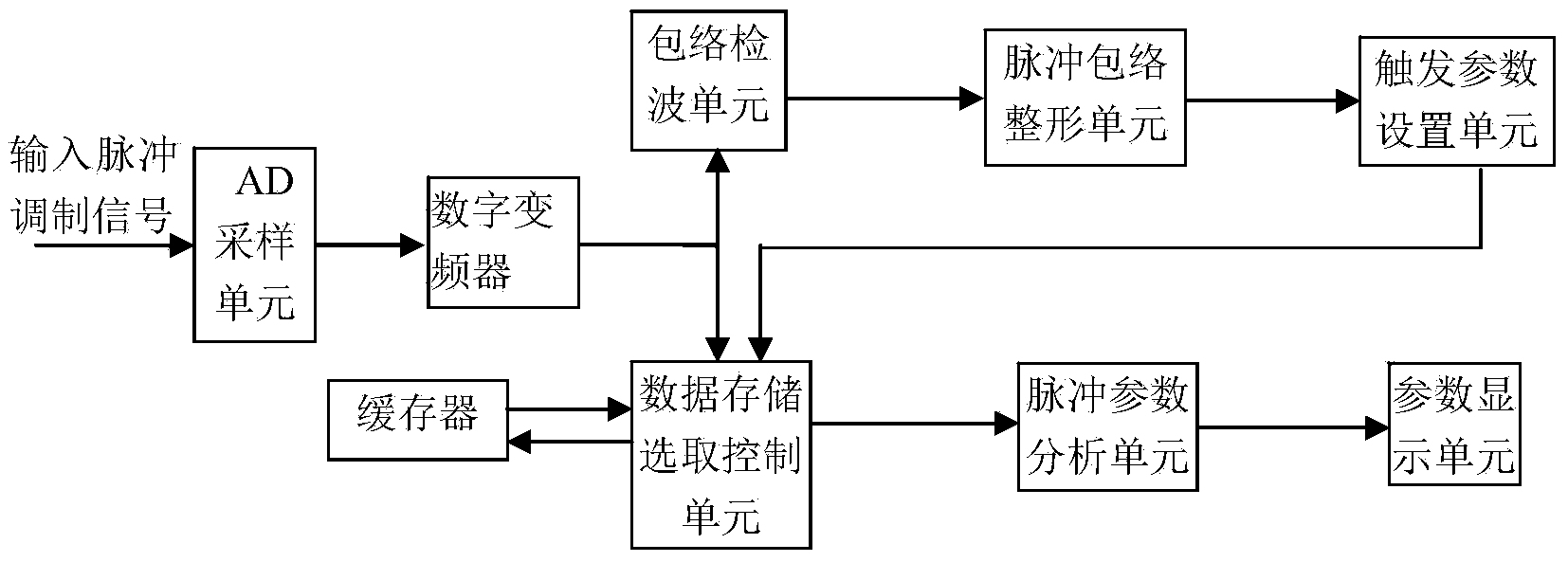
[0025] (1) The pulse modulation signal passes through the AD sampling unit to convert the analog pulse modulation signal into a sampled digital signal.

[0026] (2) The digital frequency converter performs digital mixing and filtering on the sampled digital signal and the sine and cosine signal of the same frequency as the clock, removes the pulse carrier in the signal, generates a pulse baseband signal, and reduces the data rate for easy processing.

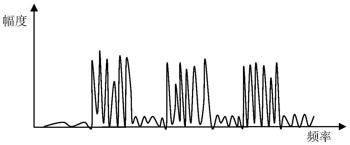
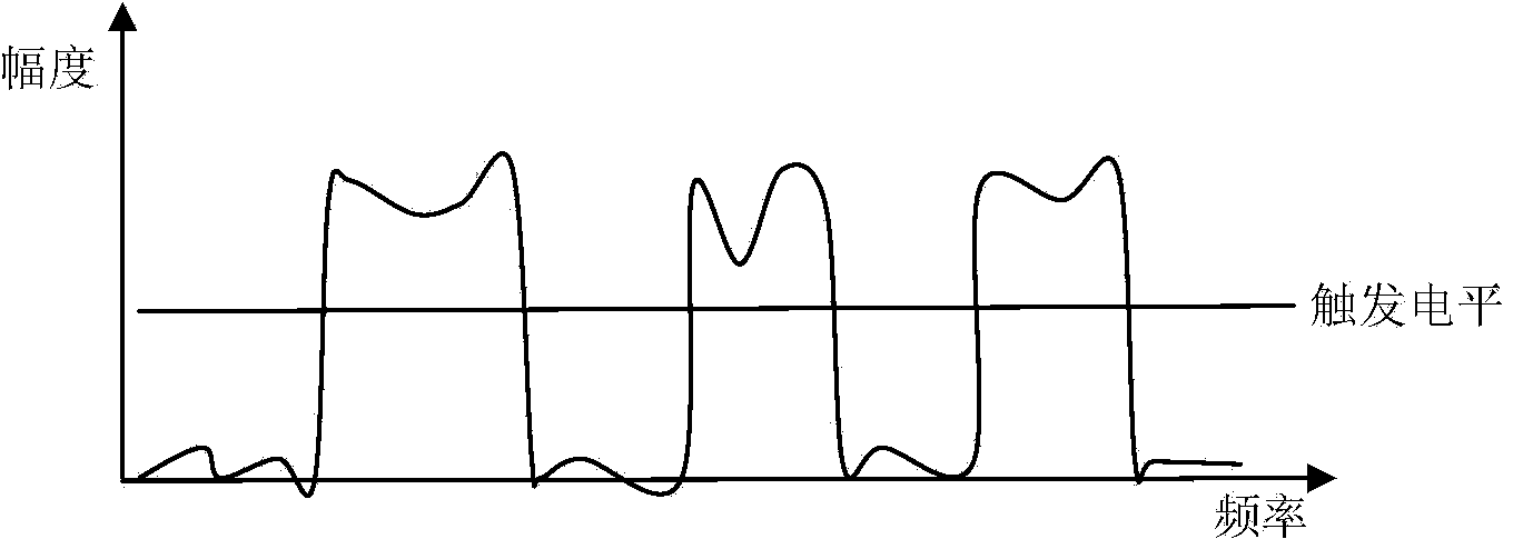
[0027] (3) The pulse baseband signal is processed in two ways, the first way is used to form the trigger pulse for data segment control selection, the pulse baseband signal passes through the envelope detection unit, the pulse envelope shaping unit, and the trigger parameter setting unit to the data storage Selection control unit; the second p...


PUM


Abstract

The invention discloses a testing method for pulse modulated signals, which comprises the following steps: (1) converting a pulse-modulated signal to a sampled digital signal through an AD sampling unit; (2) converting the sampled digital signal to a pulse baseband signal by a digital frequency converter; and (3) processing the pulse baseband signal in two paths, wherein the first path is used for forming a triggering pulse for controlling and selecting data segments, the second path is stored in a buffer through a data storage / selection control unit; (4) generating a profile envelope of the whole pulse-modulated signal by an envelope demodulating unit; (5) generating a pulse triggering signal from the profile envelope by a pulse envelope shaping unit; (6) generating a triggering data gating signal from the pulse triggering signal by a triggering parameter setting unit; and (7) outputting a corresponding pulse baseband signal to a pulse parameter analyzing unit by a the data storage / selection control unit under control by a gating signal; and performing pulse baseband signal calculation and analysis by the pulse parameter analyzing unit.

Description

technical field [0001] The invention relates to a testing method of a pulse modulation signal used in a signal analyzer. Background technique [0002] At present, signal analysis instruments input a trigger signal from the outside of the instrument, and the pulse edge of the trigger signal corresponds to the time of the signal to be analyzed, so as to trigger the signal analyzer to start scanning and sampling analysis at this time, so that the signal analysis The instrument realizes the analysis of parameters such as the targeted frequency spectrum or signal format of the signal. [0003] Disadvantages of the prior art: it is necessary to input a trigger signal from the outside of the signal analyzer, and at the same time, the trigger signal must accurately correspond to the time of the signal to be analyzed. For the signal generated by the user himself, this trigger signal can be obtained. It is difficult to obtain such time-accurate and synchronous trigger signals for pul...

Claims


Application Information

Patent Timeline
IPC IPC(8): H03K5/125H03K5/01
Inventor 王保锐许建华江炜宁刘丹
Owner CHINA ELECTRONIS TECH INSTR CO LTD
Learn More