
Waste cable recycling device

A technology for recycling devices and waste cables, which is applied in the direction of electronic waste recycling, recycling technology, equipment for dismantling/armoring cables, etc., and can solve problems such as polluting the air respiratory tract, high labor intensity, and injuries

Inactive Publication Date: 2014-08-20
DALIAN OCEAN UNIV +1
View PDF6 Cites 12 Cited by
  • Summary
  • Abstract
  • Description
  • Claims
  • Application Information

AI Technical Summary

Problems solved by technology

The manual peeling method uses manual peeling, which has low efficiency and high cost, and the operating environment for workers is poor
The incineration method is a traditional method, which burns the plastic skin of the waste cable and then recovers the copper in it, but the smoke pollution produced is extremely serious. At the same time, the surface of the copper wire is severely oxidized during the incineration process, which reduces the metal recovery. rate, and the exhaust gas after rubber burning not only pollutes the air but also seriously damages the human respiratory tract
The mechanical processing method uses a cable stripping machine for processing. This method still requires manual operation, which is semi-mechanized, labor-intensive, and inefficient. It is only suitable for processing thick-diameter cables.
One of the biggest disadvantages of chemical treatment is that the waste liquid produced by chemical reaction cannot be treated, which has a great impact on the environment, so it is rarely used

Method used


Image

  • Waste cable recycling device
  • Waste cable recycling device
  • Waste cable recycling device

Examples


Embodiment Construction

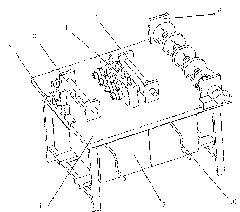
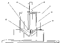
[0020] The specific implementation manner of the present invention will be described below with reference to the accompanying drawings. Such as Figure 1 to Figure 7 Shown: a waste cable recovery device, including a frame 1 as a base, on the frame 1 are sequentially arranged a primary cutter 2, a first support roller 3, a secondary cutter 4, a second support roller 5 and a winding wire Mechanism 6 is provided with a cable sheath recovery box 7 at the bottom of the frame 1. In order to improve the recovery efficiency of the cable sheath, there are two cable sheath recovery boxes 7, which are arranged side by side at the bottom of the frame 1, and each A pair of relatively rotatable driving rollers 8 and driven rollers 9 are arranged above the cable sheath recovery box 7, and a crank handle 10 is also arranged at the outer end of the driving roller 8;

[0021] The primary tool 2 includes a primary fixed frame 11 fixed at the end of the frame 1. The lower end of the primary fixe...


PUM


Abstract

The invention discloses a waste cable recycling device comprising a frame (1). The waste cable recovery device is characterized in that a first-grade tool (2), a first supporting roller (3), a second-grade tool (4), a second supporting roller (5) and a winding mechanism (6) are sequentially arranged on the frame (1), a cable sheath recycling bin (7) is arranged in the lower part of the frame (1), a driving roller (8) and a driven roller (9) which are oppositely arranged are rotationally supported above the cable sheath recycling bin (7), and a crank (10) is arranged at the outer end of the driving roller (8). In view of the problems of the existing waste cable disposing method, a special structure capable of simultaneously disposing thick outer line sheaths and thin inner line sheaths of cables is designed. Semi-automated cable stripping can be realized, the working efficiency of cable disposing is greatly improved, and no pollution is caused to the surrounding environment. Meanwhile, stripped thick line sheaths and thin line sheaths can be collected separately for centralized disposing.

Description

technical field [0001] The invention relates to a cable processing device, in particular to a waste cable recycling device. Background technique [0002] At present, cables are widely used in the fields of power system transmission, television signal transmission, etc., followed by an urgent problem to be solved is the recycling of waste cables. Every year, hundreds of thousands of tons of cables are wasted because they cannot be recycled. Resource consumption and environmental pollution force us to recycle some waste cables for reuse. [0003] At present, the methods of recycling cables mainly include manual stripping, incineration, mechanical treatment, chemical treatment and other methods. The manual peeling method adopts manual peeling, which has low efficiency and high cost, and the operating environment of the workers is relatively poor. The incineration method is a traditional method, which burns the plastic skin of the waste cable and then recovers the copper in it...

Claims


Application Information

Patent Timeline
IPC IPC(8): H02G1/12H01B15/00
CPCY02W30/82
Inventor 于功志张文孝孙琪辉姚国生惠盼盼苏露吴嵩马国振孙娜宋清霖
Owner DALIAN OCEAN UNIV
Learn More