Transformer oil tank capable of facilitating drainage and adjusting liquid level in real time

A transformer oil tank, real-time adjustment technology, applied in the direction of transformer/inductor cooling, etc., can solve the problems of reduced insulation of transformer insulating parts, poor cooling conditions, and inability to cool oil cooling.

Inactive Publication Date: 2014-08-20
平顶山电力设计院有限公司
View PDF7 Cites 16 Cited by
  • Summary
  • Abstract
  • Description
  • Claims
  • Application Information

AI Technical Summary

Problems solved by technology

The transformer oil tank currently in operation has the following deficiencies: 1) Due to design reasons, the lower plane inside the oil tank is a horizontal plane, and the installation position of the drain valve is about 40mm high from the lower plane inside the oil tank
In this way, the transformer oil in the transformer oil tank can be taken out through the drain valve when taking oil samples, but when the moisture in the atmosphere enters the transformer, due to the high temperature inside the transformer, the moisture in the atmosphere will form small Water droplets are deposited on the lower plane of the transformer oil tank. These small water droplets accumulate in small quantities. In addition, the installation position of the drain valve is about 40mm away from the lower plane of the oil tank. As a result, this part of the water cannot flow out through the drain valve. Retained in the oil tank of the transformer, the long-term existence of these moisture will definitely lead to the insulation reduction of various insulating parts inside the transformer, and will also cause the internal metal parts to corrode, causing internal discharge or even explosion of the transformer, seriously affecting the safety and stability of the transformer run
2) During the sampling process of the existing transformer oil tank, the air will inevitably enter the oil tank after the moisture is discharged, causing the moist gas to easily immerse into the oil and pollute the clean transformer oil
Its weak point is: above-mentioned cooling method can't carry out comparatively thorough cooling to the cooling oil in the oil tank, the cooling efficiency of the cooling oil in the oil tank is extremely low, the speed of cooling is slow, and cooling is unbalanced
[0008] The reason for the above-mentioned transformer explosion and fire is that the oil level in the transformer box is too low, and the cooling condition of the top of the iron core coil is poor due to the insulation part of the package. The cooling condition here is even worse, which makes the insulation overheating and aging more easily.
When the high-temperature oil gas encounters the upper high-temperature iron core, it is ejected and burned instantly. At the same time, due to the large number of holes in the flange heat ring, the oil level of the main body drops rapidly, the gap increases, the oil gas accumulates, and the air enters. At high temperature, it reaches a certain proportion and becomes explosive. The gas formed a strong explosion and caused a fire, causing heavy casualties and serious damage to equipment.

Method used


Image

  • Transformer oil tank capable of facilitating drainage and adjusting liquid level in real time
  • Transformer oil tank capable of facilitating drainage and adjusting liquid level in real time
  • Transformer oil tank capable of facilitating drainage and adjusting liquid level in real time

Examples


Embodiment 1

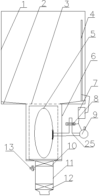
[0027] Embodiment 1: as figure 1 , 4As shown, a transformer oil tank that is convenient for drainage and real-time adjustment of the liquid level includes a tank body 1, an oil storage tank 6 connected to the tank body 1 is arranged under the tank body 1, and a connected water storage mechanism is arranged under the oil storage tank 6, so that The air bag 5 is arranged in the oil storage tank 6, and the air bag 5 communicates with the three-way valve 25 through the conduit passing through the oil storage tank. The other two ends of the three-way valve 25 are connected with a solenoid valve 8 and an electric pump 9. The pumps 9 are all connected to the programmable controller 7, and the programmable controller 7 is connected to the liquid level sensor 4 in the tank 1 through a signal line.

[0028] The water storage mechanism is a water storage cylinder 11 arranged under the oil storage tank 6 and communicated with the oil storage tank 6 , and the upper and lower ends of the w...

Embodiment 2

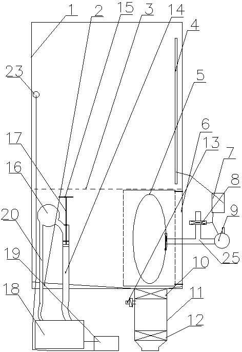
[0034] Embodiment 2: as figure 2 , 4 As shown, a transformer oil tank that is convenient for drainage and real-time adjustment of the liquid level includes a tank body 1, an oil storage tank 6 connected to the tank body 1 is arranged under the tank body 1, and a connected water storage mechanism is arranged under the oil storage tank 6, so that The air bag 5 is arranged in the oil storage tank 6, and the air bag 5 communicates with the three-way valve 25 through the conduit passing through the oil storage tank. The other two ends of the three-way valve 25 are connected with a solenoid valve 8 and an electric pump 9. The pumps 9 are all connected to the programmable controller 7, and the programmable controller 7 is connected to the liquid level sensor 4 in the tank 1 through a signal line.

[0035] The water storage mechanism is a water storage cylinder 11 arranged under the oil storage tank 6 and communicated with the oil storage tank 6 , and the upper and lower ends of the...

Embodiment 3

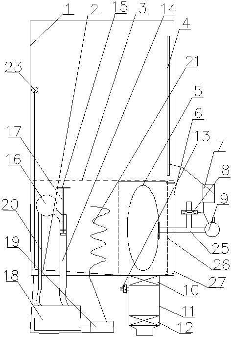
[0044] Embodiment 3: as image 3 , 4 As shown, a transformer oil tank that is convenient for drainage and real-time adjustment of the liquid level includes a tank body 1, an oil storage tank 6 connected to the tank body 1 is arranged under the tank body 1, and a connected water storage mechanism is arranged under the oil storage tank 6, so that The air bag 5 is arranged in the oil storage tank 6, and the air bag 5 communicates with the three-way valve 25 through the conduit passing through the oil storage tank. The other two ends of the three-way valve 25 are connected with a solenoid valve 8 and an electric pump 9. The pumps 9 are all connected to the programmable controller 7, and the programmable controller 7 is connected to the liquid level sensor 4 in the tank 1 through a signal line.

[0045] The water storage mechanism is a water storage cylinder 11 arranged under the oil storage tank 6 and communicated with the oil storage tank 6 , and the upper and lower ends of the ...


PUM


Abstract

The invention discloses a transformer oil tank capable of facilitating drainage and adjusting the liquid level in real time. The transformer oil tank comprises a tank body and an oil storage tank. The oil storage tank is arranged below the tank body and communicated with the tank body. A water storage mechanism communicated with the oil storage tank is arranged on the lower side of the oil storage tank. An air bag is arranged inside the oil storage tank and communicated with a three-way valve through a guiding pipe penetrating through the oil storage tank. The other two ends of the three-way valve are connected with an electromagnetic valve and an electrical pump. The electromagnetic valve and the electrical pump are both connected with a programmable logic controller. The programmable logic controller is connected with a liquid level sensor inside the tank body through a signal line. According to the transformer oil tank, the phenomena that due to the fact that the oil level of the transformer is excessively low or excessively high, the transformer breaks down, even the transformer explodes, and immeasurable losses of a power consumer and an electric power company are caused can be effectively avoid.

Description

technical field [0001] The invention belongs to the technical field of novel transformer oil tanks, and in particular relates to a transformer oil tank which is convenient for drainage and real-time liquid level adjustment. Background technique [0002] Transformers are important equipment in power systems, so ensuring the safe operation of transformers is always the top priority in our equipment maintenance work. The transformer oil tank currently in operation has the following deficiencies: 1) Due to design reasons, the lower plane inside the oil tank is a horizontal plane, and the installation position of the drain valve is about 40mm higher than the lower plane inside the oil tank. In this way, the transformer oil in the transformer oil tank can be taken out through the drain valve when taking oil samples, but when the moisture in the atmosphere enters the transformer, due to the high temperature inside the transformer, the moisture in the atmosphere will form small Wat...

Claims


Application Information

Patent Timeline
IPC IPC(8): H01F27/14
Inventor 张力淼韩国聚
Owner 平顶山电力设计院有限公司
Why Eureka
Try Eureka