
Fabrication method of circular PPTC thermistor

A thermistor and ring-shaped technology, which is applied in the field of preparation of ring-shaped PPTC thermistors, can solve the problems of uneven heating, uneven arrangement thickness, and uneven irradiation in heat treatment, so as to improve heat treatment efficiency and save Irradiation cost, good effect of resistance consistency

Active Publication Date: 2017-01-18
上海神沃电子有限公司
View PDF4 Cites 0 Cited by
  • Summary
  • Abstract
  • Description
  • Claims
  • Application Information

AI Technical Summary

Problems solved by technology

[0005] The technical problem to be solved by the present invention is to provide a heat treatment and Preparation method of circular PPTC thermistor with uniform irradiation and good consistency

Method used


Image

  • Fabrication method of circular PPTC thermistor
  • Fabrication method of circular PPTC thermistor
  • Fabrication method of circular PPTC thermistor

Examples


Embodiment 1

[0043] In this embodiment, the substrate components are 4000 g of high-density polyethylene, 4300 g of carbon black, and 1000 g of magnesium hydroxide.

[0044] Concrete method steps among the present embodiment are:

[0045] 1) Substrate treatment: Substrate batching, crushing, and mixing The substrate batching is carried out according to the above components, and then the substrate is poured into a mixer and mixed evenly.

[0046] 2) Twin-screw extruder extrusion and calendering: After mixing in step 1), the base material is vacuum-extruded and calendered by a twin-screw extruder to form a PTC plate with a thickness of 0.28 to 0.32 mm; the extrusion temperature of the twin-screw extruder is 190~200℃.

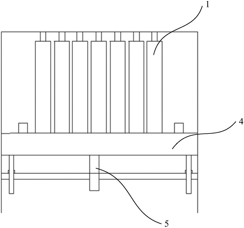
[0047] 3) After the formed plate is cooled, it is punched, and punched and cut into Φ16.3*Φ10.0 (outer circle*inner circle, unit mm) chips by punching die. Such as figure 1 As shown, a plurality of string rods 1 are arranged below the die hole of the punch die, and the ring...

Embodiment 2

[0057] As a further improvement of the present invention, in step 3), such as figure 1 As shown, a lifting plate 4 is connected to the bottom of the string rod 1 , and a jacking device 5 is arranged below the lifting plate 4 . When the lifting plate 4 rises, the skewer 1 is inserted into the mold hole. When the product is in place, the photoelectric sensor stops the punching machine, the lifting plate 4 is lowered, and a new stringer 1 is replaced. The operation is simple and convenient.

[0058] When the string rods with ring-shaped PPTC thermistors are turned over and transported, storage tools with handles on both sides are used. The distance between each layer of products is greater than 1mm, and it can be taken out in a single layer.

[0059] The preparation method of the present invention is suitable for preparing circular PPTC thermistors made of the following various raw materials. The circular PPTC thermistors include a base material and nickel-plated copper foils com...


PUM


Abstract

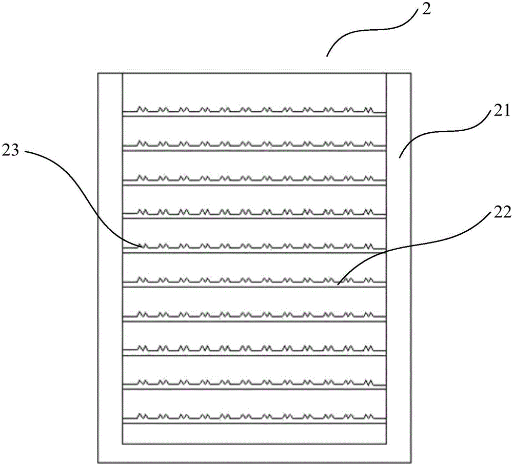
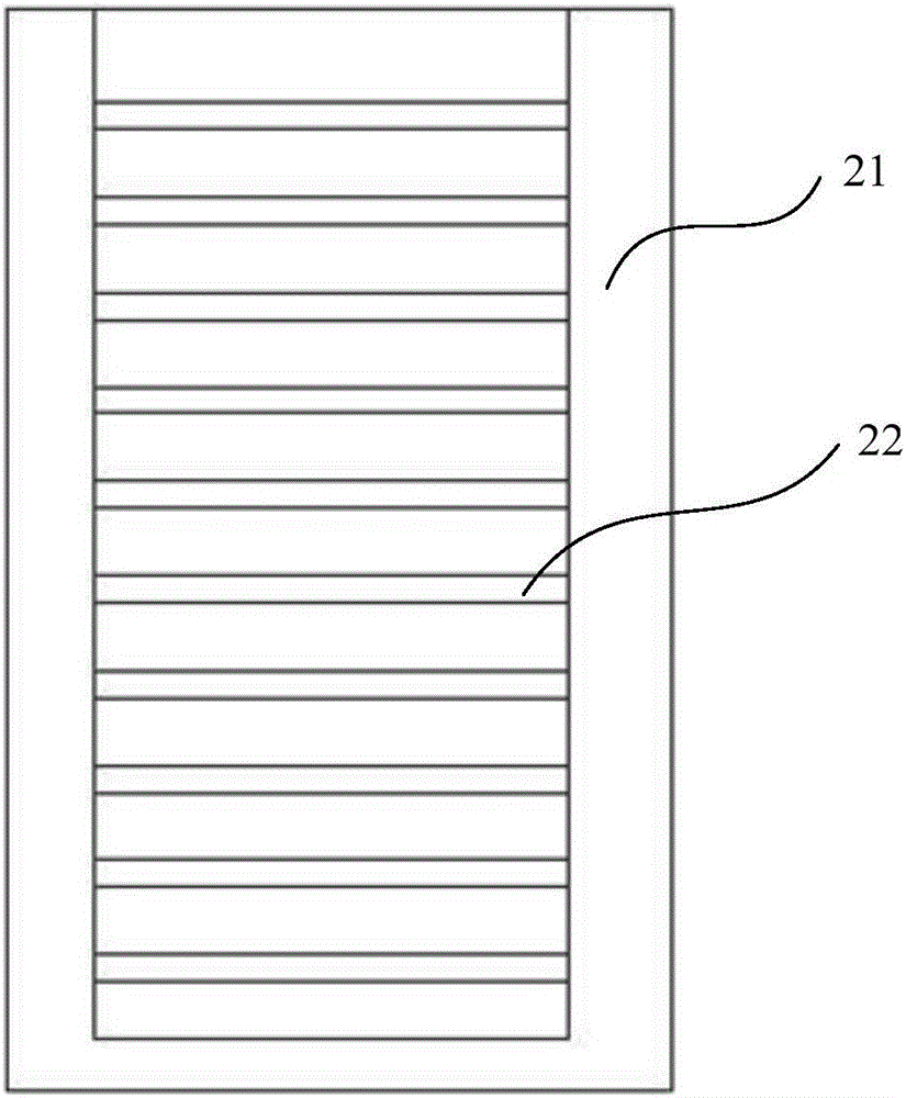
The invention provides a making method of annular PPTC thermistors. The method comprises the following steps: 1, processing a substrate; 2, carrying out extrusion calendering through a double screw extruder; 3, carrying out punching molding, arranging a plurality of loop bars below the die hole of a punch die, discharging semi-finished products, and sheathing the loop bars with the semi-finished products; 4, transferring the loop bars to a heat treatment support frame, and carrying out heat treatment in an oven; and 5, transferring the semi-finished products subjected to the heat treatment to an irradiation tool through the loop bars (wherein the irradiation tool comprises a baseboard, the front end and the rear end of the baseboard are respectively provided with a baffle board, the baffle board is provided with a plurality of gaps side by side, an irradiation area is formed between every two aligned gaps, and the bottom of the irradiation area is hollow-out), vertically arranging the semi-finished products of the circular PPTC thermistors in the irradiation zones in a row, drawing out the loop bars, and irradiating. The method realizes the punching loop bar material receiving, and the heat treatment and irradiation of the circular PPTC thermistors in a uniform ordered vertical arrangement maner, so the heat treatment heating is uniform, and the irradiation is consistent.

Description

technical field [0001] The invention relates to the field of polymer thermistors, in particular to a method for preparing an annular PPTC thermistor with heat treatment, uniform irradiation and good consistency. Background technique [0002] Polymer Positive Temperature Coefficient Thermistor (PPTC, Polymer Positive Temperature Coefficient thermistor), also known as self-recovery fuse, referred to as PPTC thermistor, PPTC thermistor is a typical temperature-sensitive resistor that exceeds a certain temperature (switching temperature ), its resistance value increases stepwise with the increase of temperature. Its working principle is: when the circuit is working normally, the resistance of the PPTC thermistor is very small and does not hinder the passage of current; when the circuit has faults such as overcurrent, overload or overheating, the temperature of the thermistor rises rapidly, and when it exceeds the switch temperature, it instantly It rises to a high-impedance sta...

Claims


Application Information

Patent Timeline
Patent Type & Authority Patents(China)
IPC IPC(8): H01C7/02
Inventor 何志勇侯李明李庆北曾贤瑞
Owner 上海神沃电子有限公司
Learn More