
Heat pipe liquid absorbing core capillary flow measuring method and device based on infrared image observation

A technology of infrared thermal imaging and flow measurement, applied in measuring devices, devices using optical methods, liquid/fluid solid measurement, etc., to achieve high measurement accuracy, low error, and simple experimental devices

Inactive Publication Date: 2014-08-20
XIAMEN UNIV
View PDF3 Cites 14 Cited by
  • Summary
  • Abstract
  • Description
  • Claims
  • Application Information

AI Technical Summary

Problems solved by technology

[0004] The purpose of the present invention is to address the defects of the existing capillary flow measurement methods, and to provide a heat pipe liquid absorption method based on infrared thermal image observation that can accurately identify the capillary flow meniscus of the heat pipe liquid suction core, and quantitatively obtain the capillary flow distance and flow rate. Core capillary flow measurement method

Method used


Image

  • Heat pipe liquid absorbing core capillary flow measuring method and device based on infrared image observation
  • Heat pipe liquid absorbing core capillary flow measuring method and device based on infrared image observation
  • Heat pipe liquid absorbing core capillary flow measuring method and device based on infrared image observation

Examples


Embodiment 1

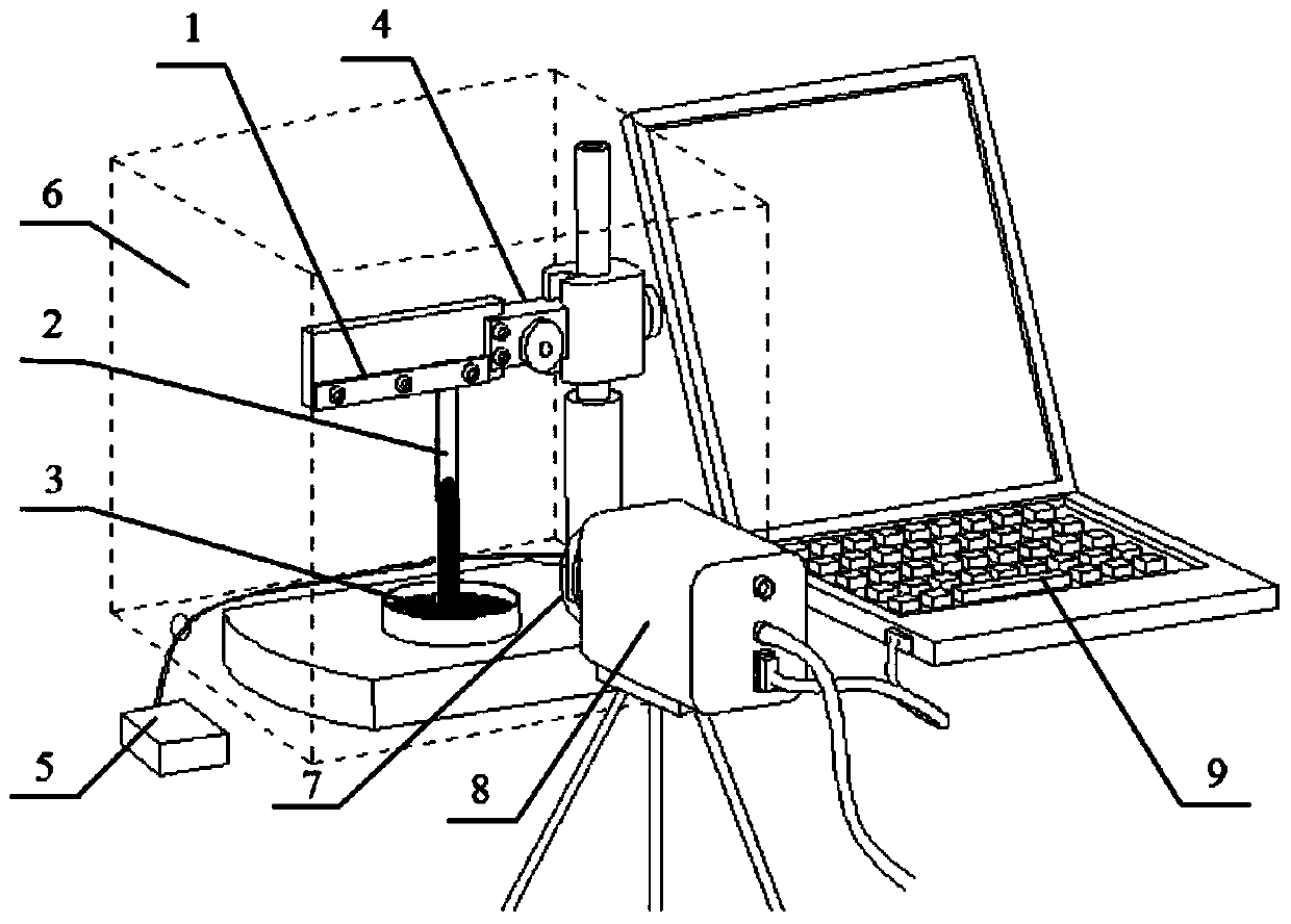
[0037] Such as figure 1 As shown, a capillary flow measurement device of a heat pipe liquid-absorbing core based on infrared thermal image observation includes a liquid-absorbing core fixing assembly 1, a working medium container 3, a moving adjustment assembly 4, an adjustment controller 5, a glass cover 6, and an infrared thermal image Instrument 8, data acquisition computer 9 and rack;

[0038] The liquid-absorbing core fixing assembly 1, liquid-absorbing core 2, working medium container 3, moving adjustment assembly 4 and frame are located in the glass cover 6; the liquid-absorbing core 2 is fixed and vertically attached to the liquid-absorbing core fixing assembly 1; The liquid core fixing component 1 is fixedly connected to the mobile adjustment component 4, and the mobile adjustment component 4 is slidably connected to the frame; the adjustment controller 5 is located outside the glass cover 6, and the adjustment controller 5 can control the mobile adjustment component ...

Embodiment 2

[0054] The difference between this embodiment and embodiment 1 is that the liquid-absorbent core 2 is placed horizontally instead of vertically, and the capillary flow length and flow rate of the liquid-absorbent core can be measured.


PUM


Abstract

The invention discloses a heat pipe liquid absorbing core capillary flow measuring method and device based on infrared image observation. The measuring method includes the steps that one end of a liquid absorbing core is fixed through a liquid absorbing core fixing assembly, the liquid absorbing core is moved through a moving and adjusting assembly, the other end of the liquid absorbing core is immersed in a liquid working medium, the flowing process of the liquid meniscus in the liquid absorbing core is accurately monitored through a glass cover hole by the adoption of a thermal infrared imager, and a monitoring record is processed to quantitatively obtain the capillary flow distance and flow speed. By using the characteristic that display effects of infrared images are different due to the emissivity difference of the liquid working medium, a metal matrix of the liquid absorbing core and a porous medium, defects of a traditional capillary flow measuring method are overcome, the heat pipe liquid absorbing core capillary flow measuring method is particularly suitable for quantitatively and accurately monitoring the capillary flow of the colorless clear liquid in the heat pipe liquid absorbing core, experimental devices are simple, measurement accuracy is high, a reliable means is provided for testing and estimating capillary performance of the heat pipe liquid absorbing core, and the expansion of the infrared thermography from a traditional thermal measurement field to the capillary flow application field is achieved.

Description

technical field [0001] The invention relates to a method and device for measuring the capillary flow of a heat pipe liquid-absorbing core, in particular to a method and a device for measuring the capillary flow of a heat pipe liquid-absorbing core based on infrared thermal image observation. Background technique [0002] With its excellent thermal conductivity, heat pipes are widely used in many fields such as aerospace, electronics, electrical machinery, construction, medical treatment, waste heat recovery, and solar and geothermal utilization. The liquid working medium in the heat pipe absorbs heat and vaporizes into steam in the evaporating section, releases heat and condenses into a liquid when it reaches the condensing section, and flows back to the evaporating section along the liquid-absorbing wick under the action of capillary pressure. Therefore, the capillary pressure of the liquid-absorbing wick is the driving force for the circulation of the working medium of the...

Claims


Application Information

Patent Timeline
IPC IPC(8): G01F23/292G01B11/02G01P3/36
Inventor 邓大祥刘晓萌万伟周伟秦利锋马盛林曾涛
Owner XIAMEN UNIV
Learn More