Rock drilling simulation test device and method for determining pressure and torque of test pole

A technology for drilling into rock simulation and test equipment, which is applied in the direction of soil material testing and material inspection products, and can solve problems such as backward test methods, rough classification, and gaps between theory and practice

Active Publication Date: 2014-08-13
TIANJIN UNIV
View PDF5 Cites 10 Cited by
  • Summary
  • Abstract
  • Description
  • Claims
  • Application Information

AI Technical Summary

Problems solved by technology

However, this classification is relatively rough. The drillability of rock depends not only on the characteristics of the rock, but also on the technical conditions of the drilling technology used. The hardness, elastoplasticity and abrasiveness of the rock directly affect the mechanical properties of the rock. Cutting abrasive materials, drill bit types, drilling equipment, drilling flushing media, the degree of perfection of the drilling process, and drilling technical conditions such as the depth, diameter, and inclination of the drilling hole will also affect the drilling performance
[0003] At present, the research on the rock drilling process is mainly theoretical research. A mathematical model is established for the form of the drill bit and the physical properties of the rock, and then a theoretical answer is obtained. Considerable simplifications have been made, such as the rigidity of the drill bit, the fracture of the rock, etc., and in order to establish the model, various hypotheses have been put forward, such as the bearing zone hypothesis, etc., which do not match the real situation of the drilling process, resulting in a gap between theory and practice. Moreover, due to the backwardness of the test method, the authenticity of the theory has not been verified.

Method used


Image

  • Rock drilling simulation test device and method for determining pressure and torque of test pole
  • Rock drilling simulation test device and method for determining pressure and torque of test pole
  • Rock drilling simulation test device and method for determining pressure and torque of test pole

Examples


Embodiment Construction

[0051] Below in conjunction with accompanying drawing and specific embodiment of the present invention will be described in further detail:

[0052] 1. The specifications of the instrument used in the test

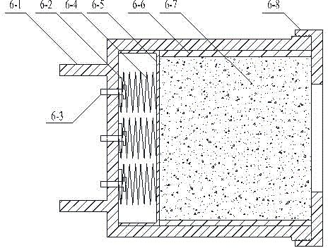
[0053] The test piece cabin 6 of the test device is composed of a canopy, a spring seat, a screw, a spring, a support plate, a steel hoop, a rock specimen and a hatch cover. The outer diameter of the canopy is 150mm, the wall thickness is 20mm, and the outer diameter of the steel hoop is 110mm, the wall thickness is 5mm, three springs are set on the spring seat, and the spring diameter is 50mm. Hatch cover, the hatch cover and the hatch cover are connected with threads.

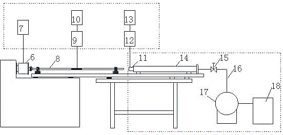
[0054] The launch rod has a diameter of 40mm and a length of 500m, and the test rod has a diameter of 40mm and a length of 500mm, all of which are made of nickel-chromium steel. E 0 2.06×10 5 MPa, shear modulus G 0 is 7.938×10 4 MPa, density ρ 0 7.1×10 3 kg / m 3 . The launch tube has an outer ...


PUM

PropertyMeasurementUnit
Diameteraaaaaaaaaa
Thicknessaaaaaaaaaa
Diameteraaaaaaaaaa

Abstract

The invention discloses a rock drilling simulation test device and a method for determining pressure and torque of a test pole, and belongs to the technical field of rock drilling research tests. The device mainly comprises a test piece cabin, the test pole, an emission rod, an emission sleeve, an air compression system and a test system, wherein a rock test piece is arranged in the test piece cabin. The method for determining the pressure and the torque of the test pole comprises the steps of enabling gas tank pressure to drive the emission rod to realize emission to collide the test pole, enabling the sharp end of a drill head of the test pole to collide the circular plane of the rotating rock test piece, collecting secondary impact loading waves Epsilon<i2>, compression waves Epsilon<r2> and torsion waves gamma of the test pole, analyzing and calculating acquired data to obtain the pressure and the torque of the test pole. The simulation test device has the characteristics of simple structure, high simulation authenticity and high test process repetitiveness, and has a test reference value and instruction significance for rock drilling engineering and scientific research.

Description

technical field [0001] The invention relates to a test device for drilling rock simulation and a method for determining the pressure and torque of a test bar, belonging to the technical field of rock drilling research and testing. Background technique [0002] Drilling into rocks is often encountered in engineering, such as geological drilling, water wells, geothermal wells, gas discharge wells, underground engineering with rocks, rotary drilling of pile foundations, etc. According to statistics, the world's core drilling The annual workload of oil and gas drilling and hydrological drilling exceeds 100 million meters, while the annual workload of mine blasting and drilling reaches hundreds of millions of meters. Rock drilling is not only a topic of theoretical research, but also an important topic of practical application research in production. In practical engineering applications, rock drillability is usually used as a quantitative index to judge the rock's ability to res...

Claims


Application Information

Patent Timeline
IPC IPC(8): G01N33/24
Inventor 夏开文陈荣谭卓英孙立强于长一李嘉
Owner TIANJIN UNIV
Why Eureka
Try Eureka