Preheating flow of high-temperature oil slurry pump

A high-temperature oil and pump technology, applied in mechanical equipment, pipeline heating/cooling, pipes/pipe joints/pipe fittings, etc., can solve problems such as wear, easy spontaneous combustion, valve erosion, etc., to achieve simple preheating process and eliminate wear Hazardous, operationally reliable effects

Active Publication Date: 2014-08-13
CHINA PETROLEUM & CHEM CORP QINGDAO RES INST OF SAFETY ENG +1
View PDF4 Cites 1 Cited by
  • Summary
  • Abstract
  • Description
  • Claims
  • Application Information

AI Technical Summary

Problems solved by technology

[0004] The technical problem to be solved by the present invention is that in the prior art, the preheating medium often contains the influence of catalyst, which inevitably causes the preheating pipelines, valves to be scoured and severely worn, and once the high-temperature oil slurry leaks, it is very easy to spontaneously ignite and catch fire. A new High temperature slurry pump preheating process

Method used


Image

  • Preheating flow of high-temperature oil slurry pump

Examples


Embodiment 1

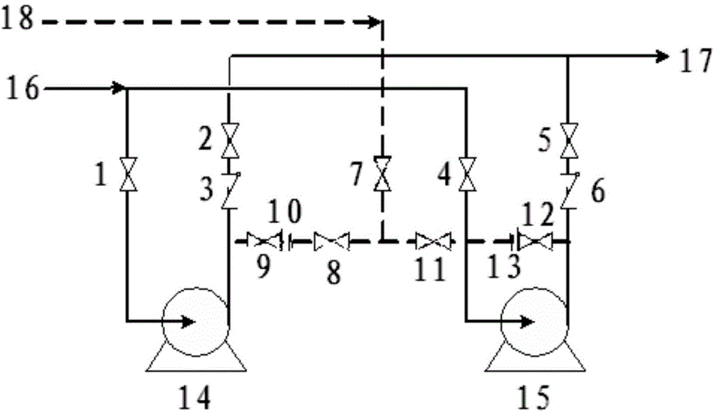
[0015] Such as figure 1 As shown, the re-refined oil at a temperature of 300°C is introduced from the preheating pipeline 18. After the main preheating valve 7, it can pass through the gate valve 8, the flow limiting orifice 10, the root cut-off valve 9 and the preheating pump 14, or pass through the gate valve 11, limiting Flow orifice 13, root cut-off valve 12 preheating pump 15; preheating main valve 7 can also be closed to communicate with gate valve 8, flow-limiting orifice 10, root cut-off valve 9 and gate valve 11, flow-limiting orifice 13, root cut-off valve 12 , realize the mutual preheating of the pump 14 and the pump 15. The medium velocity of the flow-limiting orifice 13 is about 5 m / s.

[0016] In case of an abnormal situation, the preheating line can be partially isolated by closing the main preheating valve 7, the root cut-off valve 9 and the root cut-off valve 12.

[0017] If it is found that the preheating line is not blocked smoothly, the medium reverse flo...


PUM


Abstract

The invention relates to a preheating flow of a high-temperature oil slurry pump, and mainly solves the problems that a preheating pipeline and valves are flushed and abraded unavoidably and seriously since a preheating medium commonly contains a catalyst in the prior art, and once high-temperature oil slurry leaks, spontaneous ignition is quite easily caused. By using the preheating flow of the high-temperature oil slurry pump, the preheating medium is introduced from the preheating pipeline (18), passes through a preheating main valve (7) and then is divided into two paths; one path is sequentially connected with a gate valve (8), a restriction orifice plate (10), a root cutoff valve (9) and an oil slurry pump (14), and the other path is sequentially connected with a gate valve (11), a restriction orifice plate (13), a root cutoff valve (12) and an oil slurry pump (15). According to the technical scheme, the problems are better solved. The preheating flow of the high-temperature oil slurry pump can be used for preheating the high-temperature oil slurry pump.

Description

technical field [0001] The invention relates to a high-temperature oil slurry machine pump preheating process. Background technique [0002] The catalytic cracking process is a typical petroleum secondary processing device. The safe operation of the oil slurry system plays a vital role in the device. In order to improve the operation reliability, the oil slurry pump usually adopts the configuration of one for one standby or one for two standbys . To reach the standby state, the high-temperature pump needs to be preheated to a certain temperature, and the high-temperature medium is always in the circulation and flow mode to achieve hot standby. [0003] Chen Junwu et al. (Catalytic Cracking Technology and Engineering, Second Edition, China Petrochemical Press, 2005) described the preheating method of the high-temperature oil slurry pump. Usually, the high-temperature and high-pressure medium from the outlet of the pump is introduced to the inlet of the standby pump, and then...

Claims


Application Information

Patent Timeline
Patent Type & Authority Applications(China)
IPC IPC(8): F16L53/00
CPCF16L53/32
Inventor 王家见韩中枢路荣博卢卫宋建国张弘王建伟
Owner CHINA PETROLEUM & CHEM CORP QINGDAO RES INST OF SAFETY ENG
Why Eureka
Try Eureka