Hydraulic steering booster device for UAV steering gear

A technology of booster device and hydraulic pressure, which is applied to the power device, aircraft transmission device, aircraft power transmission and other directions of the aircraft, can solve the problems of high oil precision, high cost and high system failure rate, and achieves low cost and reduced burden. , the effect of simple connection

Active Publication Date: 2016-02-24
HARBIN
View PDF6 Cites 0 Cited by
  • Summary
  • Abstract
  • Description
  • Claims
  • Application Information

AI Technical Summary

Problems solved by technology

[0005] (3) The electro-hydraulic servo valve (or proportional valve) has high requirements on oil precision, high system failure rate, and high cost

Method used


Image

  • Hydraulic steering booster device for UAV steering gear

Examples


Embodiment Construction

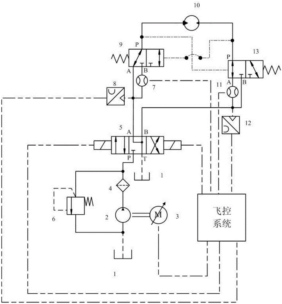
[0017] The present invention will be described in detail below in conjunction with the accompanying drawings.

[0018] The hydraulic control booster device for the UAV steering gear includes fuel tank 1, quantitative hydraulic pump 2, frequency conversion motor 3, oil filter 4, three-position four-way solenoid valve 5, overflow valve 6, left flow sensor 7, left pressure sensor 8, left Hydraulically controlled two-position three-way reversing valve 9, steering gear booster motor 10, right flow sensor 11, right pressure sensor 12, right hydraulically controlled two-position three-way reversing valve 13. The drive shaft of the quantitative hydraulic pump 2 is connected to the output shaft of the variable frequency motor 3, the oil suction port of the quantitative hydraulic pump 2 is connected to the oil tank 1, the oil outlet of the quantitative hydraulic pump 2 is connected to the oil filter 4, and the other ends of the oil filter 4 are respectively It is connected with the oil ...


PUM


Abstract

The invention belongs to the hydraulic technology of an unmanned aerial vehicle, and relates to a hydraulic control assisting device for a steering engine of the unmanned aerial vehicle. The hydraulic control assisting device for the steering engine of the unmanned aerial vehicle, provided by the invention, uses a quantitative hydraulic pump controlled by a frequency conversion motor as a pressure source to brake, a driving shaft of the quantitative hydraulic pump does not need to be connected with an engine shaft, the connecting manner is simple, and the position where the device is mounted is unrestricted. The turning-on and the output flow of the quantitative hydraulic pump are controlled by controlling the output rotational speed of the frequency conversion motor, so that the energy consumption is low. Through the use of liquid controlled two-position tee reversing valves, flow sensors can be located in an oil return path of a system all the time, so that the detecting accuracy for the system is improved. The reversing valves which are low in cost and have low requirements for oil liquid accuracy are selected and used for the assisting device, so that the failure rate of the assisting device is low. By mounting a kind of flow sensors for the assisting device for detection of the speed and the displacement of the steering engine at the same time, the burden of a flight control system is reduced. Pressure sensors are mounted for detecting the pressure of the system, so that a control system can understand the real-time information of the control assisting device.

Description

technical field [0001] The invention belongs to the hydraulic technology of an unmanned aerial vehicle, and relates to a hydraulic control booster device for an unmanned aerial vehicle steering gear. Background technique [0002] In the existing UAV steering gear hydraulic control booster device, the electro-hydraulic control servo hydraulic system is generally used, and the flow and pressure of the system are controlled by controlling the opening of the electro-hydraulic servo valve (or proportional valve) to realize the steering gear steering booster. , the speed and displacement of the steering gear are detected by the speed sensor and the displacement sensor. The structure is heavy and complex, and many signals need to be detected. This approach has 3 disadvantages: [0003] (1) The installation position is limited: the hydraulic pump shaft must be connected to the engine shaft, there is no choice for the position of the hydraulic pump, and the connection process betwee...

Claims


Application Information

Patent Timeline
Patent Type & Authority Patents(China)
IPC IPC(8): B64C13/40
Inventor 谷峰王洪志杜荃朱博张卓然杨晓亮
Owner HARBIN
Why Eureka
Try Eureka