
Method and jig for attaching bare chip to IC (Integrated Circuit) substrate

A carrier board and bare crystal technology, which is applied in the field of IC carrier board bare chip mounting and fixtures, can solve problems such as lack of positioning, material loss, and inaccurate positioning, so as to improve mounting accuracy and reflow soldering The effect of improving quality, reducing operating movements, and improving precision

Active Publication Date: 2014-08-06
SUZHOU ETRON TECH CO LTD
View PDF8 Cites 8 Cited by
  • Summary
  • Abstract
  • Description
  • Claims
  • Application Information

AI Technical Summary

Problems solved by technology

[0009] (1) Use high-temperature tape to fix the IC carrier board. After the welding is completed, the high-temperature tape cannot be used again, resulting in a large loss of the material;
[0010] (2) Positioning pins cannot be used for positioning, because the IC carrier board is relatively thin, usually below 0.4mm, so when designing the positioning pins, if the positioning pins are too high, it will directly affect the subsequent screen printing process, which is It is required that the positioning column cannot be higher than the thickness of the IC carrier board, and such a low positioning column cannot be inserted into the positioning hole of the IC carrier board when the IC carrier board is warped, and the positioning effect cannot be achieved;
[0011] (3) When using the outline of the IC substrate for positioning, the accuracy of positioning depends largely on the deviation of the shape of the IC substrate, so the problem of inaccurate positioning is prone to occur;
[0012] (4) After using high-temperature tape to fix the IC carrier board, only the edge of the IC carrier board is fixed, and the middle part of the IC carrier board will have protrusions or undulations, which directly affect the bare chip mounting The quality and quality of reflow soldering

Method used


Image

  • Method and jig for attaching bare chip to IC (Integrated Circuit) substrate
  • Method and jig for attaching bare chip to IC (Integrated Circuit) substrate
  • Method and jig for attaching bare chip to IC (Integrated Circuit) substrate

Examples


Embodiment Construction

[0039] The specific implementation manners of the present invention will be further described below in conjunction with the drawings and examples. The following examples are only used to illustrate the technical solution of the present invention more clearly, but not to limit the protection scope of the present invention.

[0040] The technical scheme of concrete implementation of the present invention is:

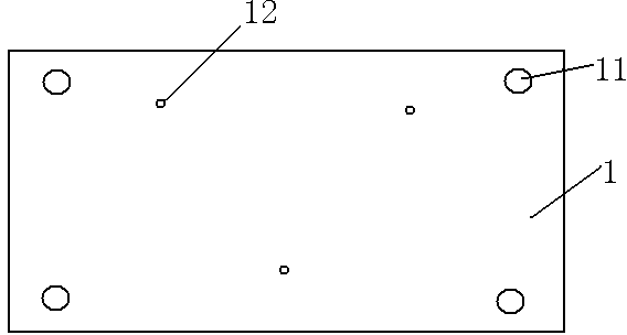
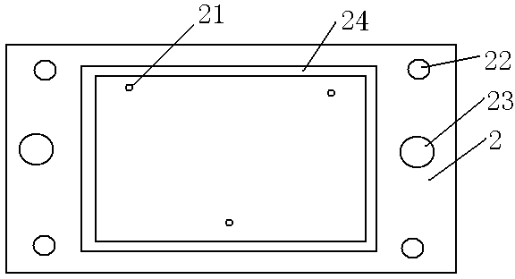
[0041] Such as Figure 1-Figure 3 As shown, a jig for mounting bare chips on an IC carrier, including a base 1, a tray 2, an adhesive material and a cover 3;

[0042] The base 1 is used to place the tray 2 horizontally; the top surface of the base 1 is provided with: a tray positioning column 11, and an IC carrier positioning column 12 correspondingly matched with the positioning holes of the IC carrier; the IC carrier The number of positioning columns 12 is three, which are distributed in a triangle, which can not only be accurately positioned, but also can be fool-proo...


PUM


Abstract

The invention discloses a method and jig for attaching a bare chip to an IC (Integrated Circuit) substrate. The jig comprises a base, a tray, a sticking material and a cover plate. By adopting the method and the jig disclosed by the invention, the defects in the process of attaching of the bare chip to the IC substrate can be overcome.

Description

technical field [0001] The invention relates to a method and a jig for mounting a bare chip on an IC carrier board. Background technique [0002] The IC substrate is mainly used to carry the bare chip, and there are lines inside to conduct the signal between the chip and the circuit board. In addition to the function of carrying, the IC substrate also has protection circuits, dedicated lines, and designed heat dissipation channels , Establish additional functions such as component modularization standards. [0003] At present, the common methods and steps for mounting bare chips on IC carrier boards are mainly: jig preparation→IC carrier board fixing→bare chip mounting→IC carrier removal. [0004] (1) Fixture (tray) preparation: Make the fixture. The material of the fixture is aluminum alloy, because the material has a small thermal deformation coefficient and high hardness, which prevents deformation after repeated use. The commonly used positioning method is to directly ...

Claims


Application Information

Patent Timeline
Patent Type & Authority Applications(China)
IPC IPC(8): H05K3/34
Inventor 孙中华陈献祥
Owner SUZHOU ETRON TECH CO LTD
Learn More