
Reactive compensation optimization method of 400V distribution network areas per transformer

An optimization method and technology of the station area, applied in the direction of reactive power compensation, reactive power adjustment/elimination/compensation, special data processing applications, etc., can solve the problems of complex and inaccurate reactive power compensation processing data, and achieve intelligent wireless Function characteristic screening, benefit optimization, and the effect of improving accuracy

Active Publication Date: 2014-08-06
GUANGZHOU POWER SUPPLY BUREAU GUANGDONG POWER GRID CO LTD
View PDF3 Cites 16 Cited by
  • Summary
  • Abstract
  • Description
  • Claims
  • Application Information

AI Technical Summary

Problems solved by technology

[0005] In view of the complex or inaccurate processing data of reactive power compensation in the existing 400V distribution network area, the present invention provides a reactive power compensation optimization method in the 400V distribution network area, which can optimize the reactive power compensation in the distribution network area , to improve the accuracy of reactive power compensation in the distribution network area

Method used


Image

  • Reactive compensation optimization method of 400V distribution network areas per transformer
  • Reactive compensation optimization method of 400V distribution network areas per transformer
  • Reactive compensation optimization method of 400V distribution network areas per transformer

Examples


Embodiment Construction

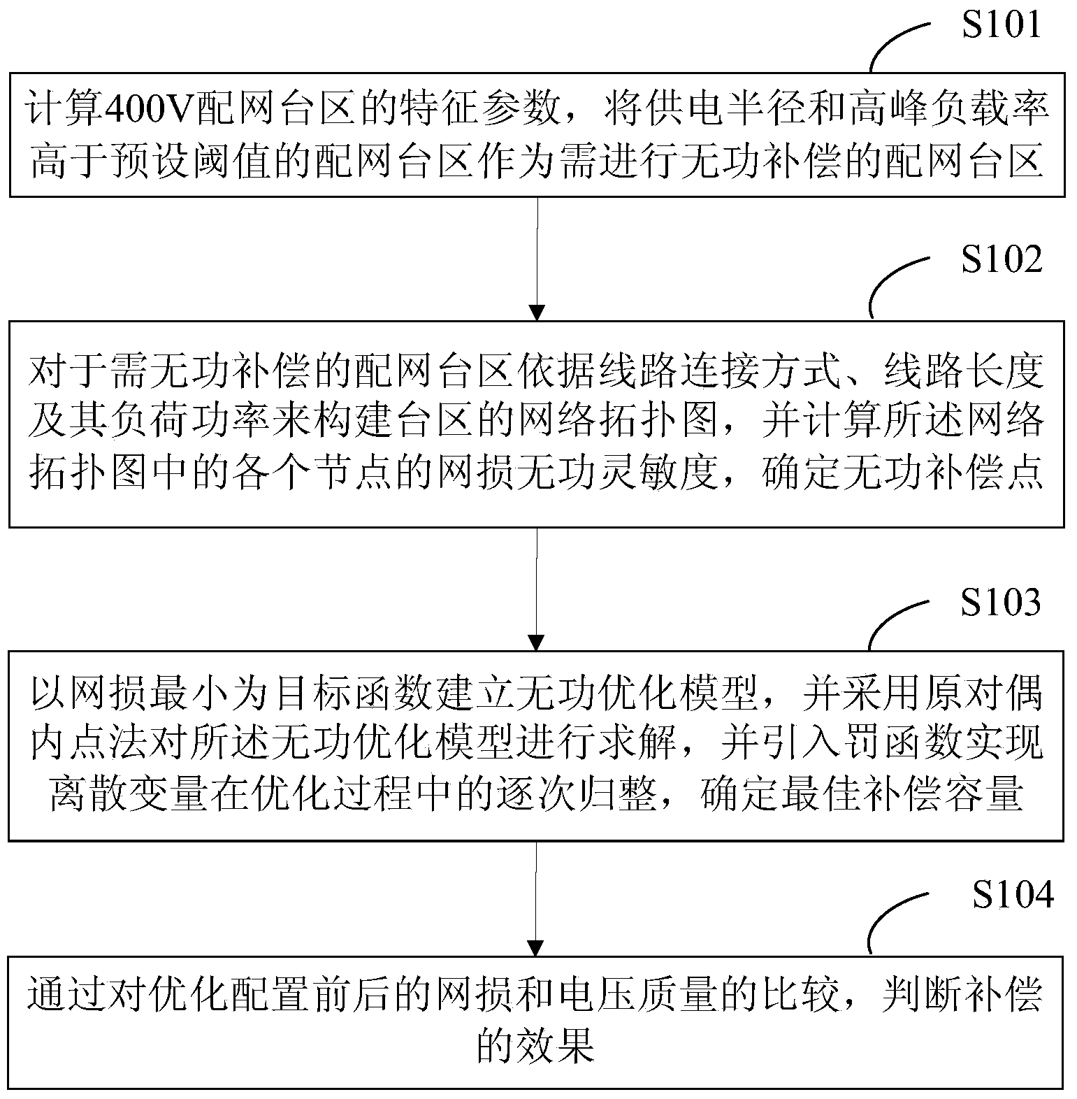
[0018] see figure 1 , figure 1 It is a schematic flow chart of the reactive power compensation optimization method for the 400V distribution network station area of ​​the present invention.

[0019] A method for optimizing reactive power compensation in a 400V distribution network station area, comprising the following steps:

[0020] S101, calculate the characteristic parameters of the 400V distribution network station area, and use the distribution network station area whose power supply radius and peak load rate are higher than the preset threshold as the distribution network station area requiring reactive power compensation;

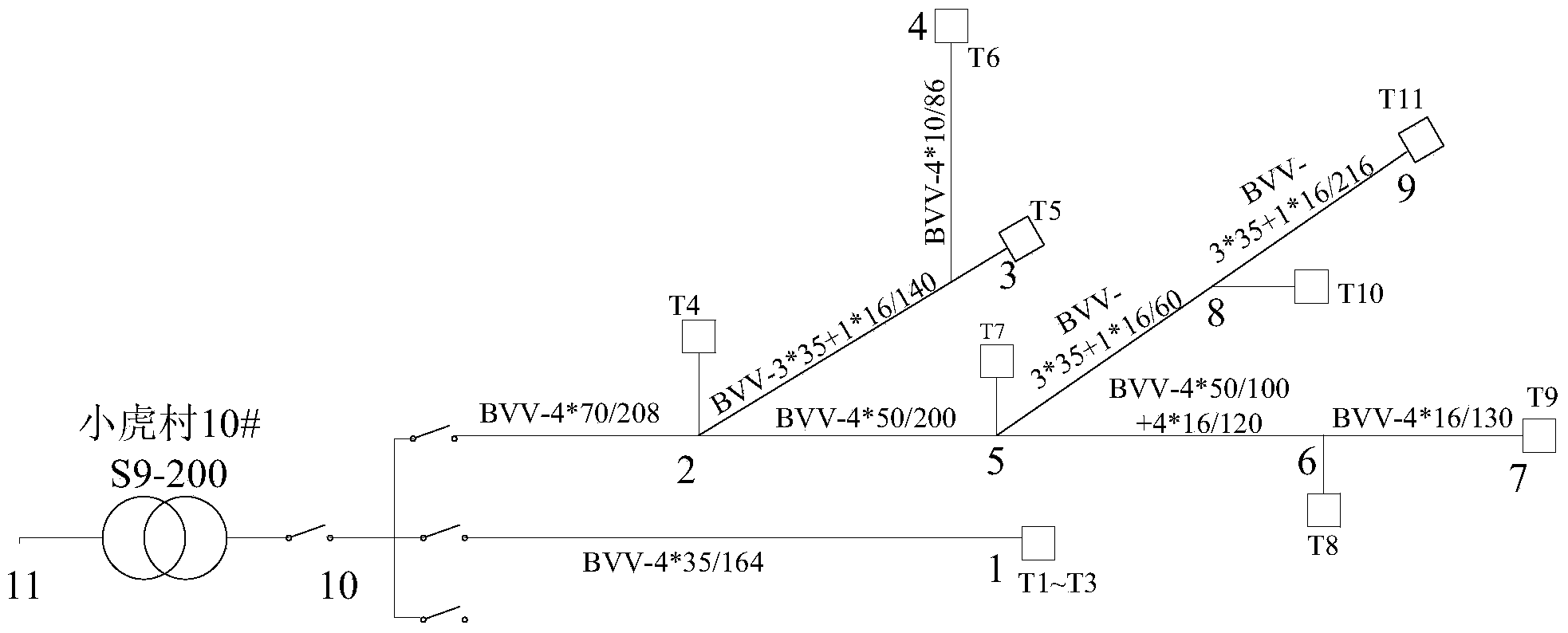
[0021] S102, constructing a network topology diagram of the distribution network station area requiring reactive power compensation according to the line connection mode, line length and load power thereof, and calculating the network loss reactive power sensitivity of each node in the network topology map, Determine the reactive power compensatio...


PUM


Abstract

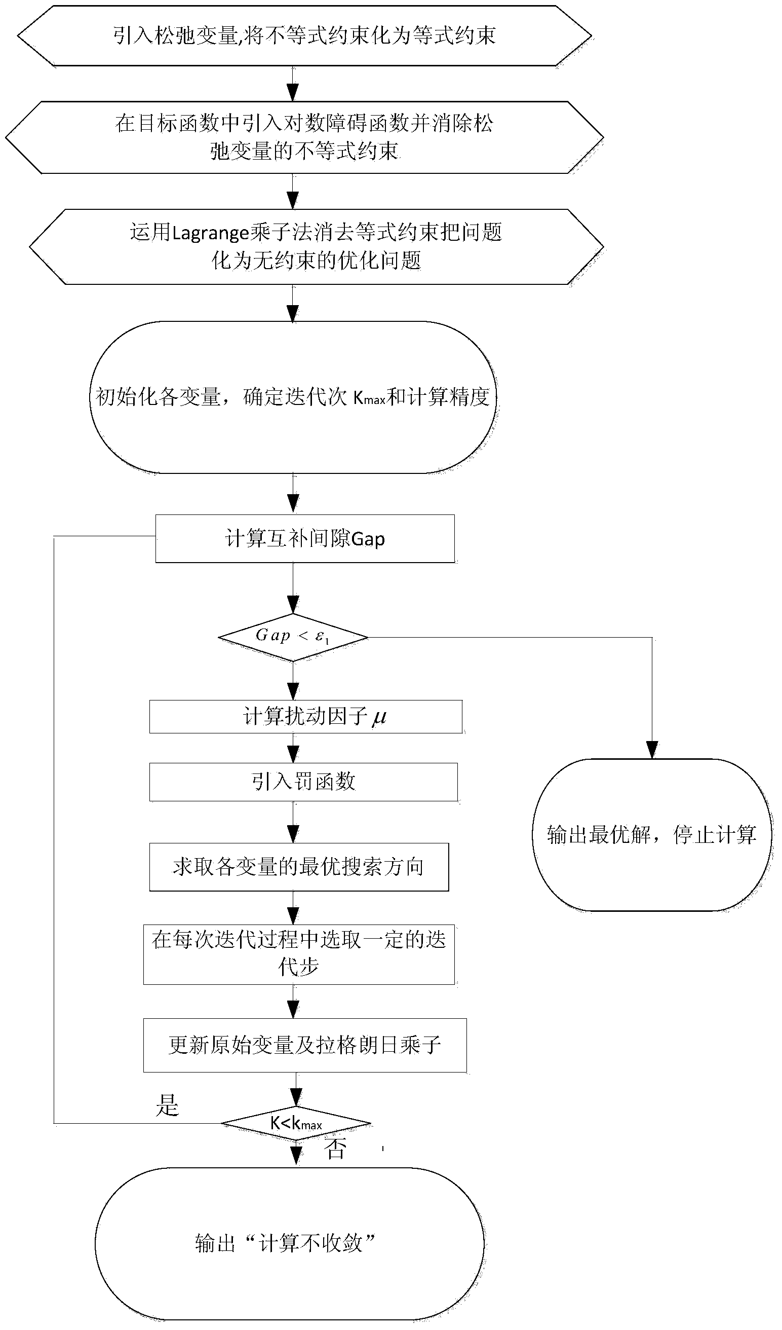
The invention provides a reactive compensation optimization method of 400V distribution network areas per transformer. The characteristic parameters of the 400V distribution network areas per transformer are calculated, and distribution network areas per transformer with the power supply radius and the peak load rate higher than preset thresholds serve as the distribution network areas per transformer requiring reactive compensation; for the distribution network areas per transformer requiring reactive compensation, a network topological graph of the areas per transformer is constructed according to the line connecting mode, the line length and the load power of the distribution network areas per transformer, the network loss reactive sensitivities of all nodes in the network topological graph are calculated, and reactive compensation points are determined; a reactive optimization model is established with the smallest network loss as a target function, the reactive optimization model is solved through a prime-dual interior point method, a penalty function is introduced to achieve successive warping of a discrete variable in the optimization process, and the best compensation capacity is determined; by comparing the network loss and the voltage quality before and after the optimization configuration, the compensation effect is judged. Through the method, reactive compensation for the distribution network areas per transformer can be optimized, and the accuracy of reactive compensation for the distribution network areas per transformer can be improved.

Description

technical field [0001] The invention relates to the technical field of reactive power compensation in a distribution network, in particular to an optimization method for reactive power compensation in a 400V distribution network station area. Background technique [0002] The overall characteristics of the 400V distribution network area are long lines, small line diameters, and insufficient reactive power compensation, which leads to large line losses and significantly low voltage in some areas. However, in practical applications, in order to save energy and reduce emissions, it is necessary to reduce line network loss, and users have increasingly stringent requirements for voltage quality. If the voltage exceeds the upper or lower limit, the equipment will stop running or even be damaged, and there is a greater risk. Therefore, it is very necessary to screen out the 400V distribution network area that needs reactive power compensation urgently and optimize the compensation ...

Claims


Application Information

Patent Timeline
IPC IPC(8): H02J3/18G06F17/50
CPCY04S10/545Y02E60/76Y02E40/76Y02E40/30Y04S40/22
Inventor 黄晓彤欧阳森黎洪光耿红杰陈文炜林舜江梁立峰李玉荣
Owner GUANGZHOU POWER SUPPLY BUREAU GUANGDONG POWER GRID CO LTD
Learn More