Eureka AIR delivers breakthrough ideas for toughest innovation challenges, trusted by R&D personnel around the world.

Method for rapidly diagnosing unmanned helicopter sensor faults

A sensor failure, unmanned helicopter technology, applied in the direction of instruments, special data processing applications, electrical digital data processing, etc., to achieve the effect of low false alarm rate and false alarm rate

Active Publication Date: 2014-08-06
NANCHANG HUAMENGDA AVIATION TECH DEV
View PDF3 Cites 22 Cited by
  • Summary
  • Abstract
  • Description
  • Claims
  • Application Information

AI Technical Summary

Problems solved by technology

For such a system, the general observer or filter method cannot effectively complete the sensor fault diagnosis of the unmanned helicopter flight control system

Method used


Image

  • Method for rapidly diagnosing unmanned helicopter sensor faults
  • Method for rapidly diagnosing unmanned helicopter sensor faults
  • Method for rapidly diagnosing unmanned helicopter sensor faults

Examples


Embodiment Construction

[0022] In order to further clarify the present invention in detail, the following describes in detail in conjunction with the accompanying drawings and preferred embodiments.

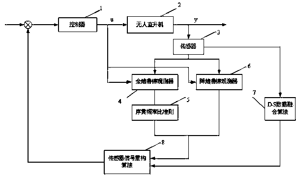
[0023] Usually, as figure 1 As shown, the controller (1) and the sensor (3) set on the unmanned helicopter (2) are used as the linear steady-state flight control system of the unmanned helicopter (2), which can be described by the following state space model.

[0024] (1)

[0025] In the formula, is the state vector; is the control vector; is the observation vector (or the output vector of the sensor), , , is a constant matrix of the corresponding dimension.

[0026] When the system fails, the above model will change accordingly. Generally, sensor fault types include stuck, gain change, constant deviation and other fault types. The above sensor fault behavior will affect the dynamic performance of the closed-loop feedback system, so it is necessary to perform fault diagnosis and fault-...


PUM


Abstract

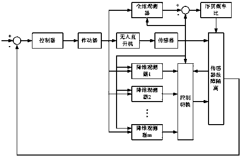
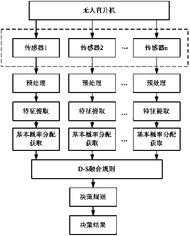
The invention provides a method for rapidly diagnosing unmanned helicopter sensor faults. The method is characterized in that an estimated value of a full-dimensional robust observer is compared with actual values measured by sensors to generate residual errors, decision-making analysis is carried out on the residual errors with a sequential likelihood ratio criterion, and the system faults are accordingly detected; meanwhile, a series of parallel dimensionality reduction robust observers are built for the sensors participating in signal feedback to achieve decoupling on output signals, then the output signals of the sensors are compared with estimated values of the dimensionality reduction robust observers, and the sensor with the maximum residual error deviation is a fault sensor. The types of the faults are rapidly determined by fault types of multi-sensor D-S data fusing algorithms.

Description

technical field [0001] The invention relates to a method for rapidly and accurately detecting and locating sensor faults of an unmanned helicopter flight control system, which belongs to the technical field of aerospace unmanned aerial vehicles. Background technique [0002] The fault diagnosis method based on the analytical model is one of the mainstream methods at present and in the future. Its idea is to use the existing knowledge to establish a mathematical model of the system, transfer the input and output of the system to the mathematical model at the same time, and use certain criteria to establish the residual of the system. Poor, and then determine whether the system has a fault, what fault has occurred and the size of the fault according to certain criteria. Among them, the method based on observer and parameter estimation is one of the most commonly used methods. Its basic idea is based on the measured value, by using an observer in a deterministic system or a Kal...

Claims


Application Information

Patent Timeline
Patent Type & Authority Applications(China)
IPC IPC(8): G06F19/00G05B23/02
Inventor 贾杰徐卫平涂世武
Owner NANCHANG HUAMENGDA AVIATION TECH DEV
Why Eureka
Eureka Blog
Learn More