A special anti-glare optical lens for drivers and its manufacturing method

A technology of optical lenses and manufacturing methods, applied in optics, filters, optical components, etc., can solve the problems of inability to clearly distinguish the numbers of the countdown of traffic lights, no protection against strong light and ultraviolet rays for ordinary people, and poor recognition ability of traffic lights at night, etc. , to maintain the clarity and authenticity of vision, ensure human health, and relieve visual fatigue.

Active Publication Date: 2016-04-13
OURLOOK ZHANGZHOU OPTICAL TECH
View PDF7 Cites 0 Cited by
  • Summary
  • Abstract
  • Description
  • Claims
  • Application Information

AI Technical Summary

Problems solved by technology

What is even more troublesome is that some myopic drivers are particularly sensitive to lights when driving at night. When the strong light from the high beam of the other car hits the driver's eyes, it will cause glare, causing blind spots to appear in front of the eyes, and traffic lights at intersections The recognition ability at night is very poor, and the countdown numbers of traffic lights cannot be clearly distinguished, especially for drivers with myopia and astigmatism; this is very dangerous for driving at night; but we can choose a professional driver The anti-glare optical mirror lens makes the visual effect easy and clear, and the resolution is improved, which provides multiple insurances for people's travel safety, and provides one more visual protection for the strong light encountered in work
The optical lenses currently on the market generally have a single function, mainly for vision correction without the function of preventing glare and ultraviolet rays, and there are no flat lenses or optical lenses suitable for ordinary people to prevent glare and ultraviolet rays

Method used


Image

  • A special anti-glare optical lens for drivers and its manufacturing method

Examples


Embodiment 1

[0073] Example 1: 20% silicon oxide and 80% zirconium oxide.

Embodiment 2

[0074] Embodiment 2: silicon oxide 80%, zirconium oxide 20%.

Embodiment 3

[0075] Example 3: 50% silicon oxide and 50% zirconium oxide.

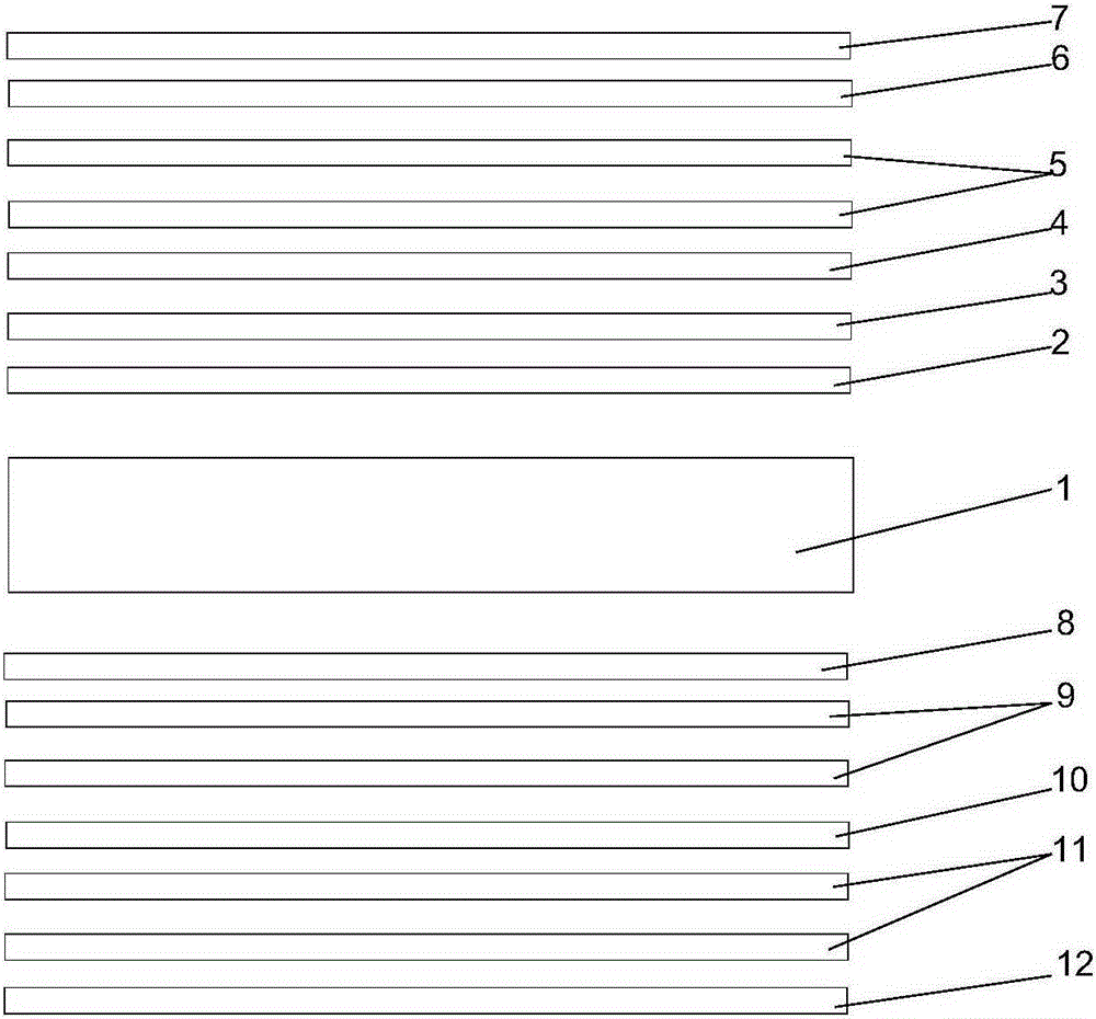
[0076] Embodiment of the anti-blue light film layer 4 components on the outer surface of the substrate 1:

[0077] Embodiment 1: tin oxide 30%; rubidium 40%; platinum 40%.

[0078] Embodiment 2: tin oxide 60%, rubidium 10%; platinum 30%.

[0079] Embodiment 3: tin oxide 55%, rubidium 35%; platinum 10%.

[0080] The embodiment of the anti-glare film layer 5 components on the outer surface of the substrate 1:

[0081] Example 1: 30% indium tin oxide; 40% rubidium; 10% platinum; 20% dysprosium.

[0082] Example 2: Indium tin oxide 60%; Rubidium 10%; Platinum 40%; Dysprosium 10%.

[0083] Example 3: 50% indium tin oxide; 30% rubidium; 25% platinum; 15% dysprosium.

[0084] Embodiments of the components of the optical regulation film layer 6 on the outer surface of the substrate 1:

[0085] Example 1: Aluminum 40%, silicon oxide 60%.

[0086] Embodiment 2: aluminum 60%, silicon oxide 40%.

[0087] Embodiment 3: ...


PUM


Abstract

An anti-glare optical lens dedicated for a driver and a manufacturing method therefor. Both an outer surface and an inner surface of a substrate (1) are coated with a plurality of films, comprising anti-impact strengthening films (2, 8), anti-ultraviolet films (3, 9), blue light proof films (4, 10), anti-glare films (5, 11), an optical control film (6) and anti-oil pollution protection films (7, 12) from inside to outside in sequence. The outer surface and the inner surface are both coated with more than one anti-glare film, thereby strengthening the anti-glare effect of the lens. The manufacturing method is to form an anti-glare optical lens by respectively evaporating film systems on an outer surface and an inner surface of a substrate(1). The manufacturing method comprises the steps of: 1) cleaning a substrate (1); 2)drying the cleaned substrate (1); 3) cleaning the substrate (1) once again in a vacuum chamber of an electron beam evaporator before coating; and 4) coating the substrate (1): coating the substrate (1) comprises coating a film system on the outer surface of the substrate (1) and on the inner surface of the substrate (1). The anti-glare optical lens has the function of preventing harmful hard light and ultraviolet rays from hurting the human body to enable a driver to drive more securely, and also has the functions of anti-oil pollution and autonomous optical control.

Description

technical field [0001] The invention relates to a driver-specific anti-glare optical lens and a manufacturing method thereof. Background technique [0002] With the change of modern life style, we face the stimulation of strong light for a long time every day, such as high beams of cars, computers, TVs, mobile phones, LED lights, outdoor sunlight, etc. Little do they know that these strong lights have short wavelengths and high energy, which can easily cause dry eyes, photophobia, fatigue and other premature cataracts and spontaneous macular degeneration. Strong light exists in (280-780 nanometers) and accounts for about 50-60% of visible light, and the high beam lights of cars have always troubled people's daily life, especially at night when you drive a vehicle on the road and encounter a car The strong light of the high beam lights will seriously affect your vision at this time. The blind spot in the line of sight will easily cause traffic hazards, especially on the expr...

Claims


Application Information

Patent Timeline
Patent Type & Authority Patents(China)
IPC IPC(8): G02B5/20G02B1/18G02B1/10
CPCG02B1/10G02C7/10
Inventor 吴晓彤
Owner OURLOOK ZHANGZHOU OPTICAL TECH
Why Eureka
Try Eureka