
Vacuum photoelectric direct-reading spectrometer

A photoelectric direct reading and spectrometer technology, applied in instruments, scientific instruments, electrical excitation analysis, etc., can solve the problems of wasting energy, unable to analyze immediately, reducing structural hardness, etc., to avoid easy damage.

Active Publication Date: 2014-08-06
JIANGSU XINZHIYUAN INSTR
View PDF8 Cites 7 Cited by
  • Summary
  • Abstract
  • Description
  • Claims
  • Application Information

AI Technical Summary

Problems solved by technology

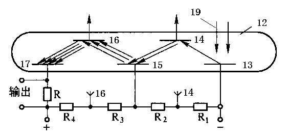
[0004] figure 2 It is a schematic diagram of the structure of a traditional photomultiplier tube. Its structure is relatively simple, but for multiple (general photomultiplier tubes have 7 to 12) secondary electron emitters, the shell of the PMT is too long. Most of the outer casings are glass structures, which are easily damaged and the overall structure hardness is reduced
[0005] In addition, in the process of use, it takes a certain amount of time for the photomultiplier tube to reach a stable working state, generally about two hours, so the analysis cannot be performed immediately after the high voltage is turned on, otherwise the analysis result will be too large.
The current measures are to apply high voltage to the photomultiplier tube all the time, and use the fatigue lamp to keep the photomultiplier tube in working condition for a long time. Obviously, it will not only reduce the service life of the photoelectric direct reading spectrometer, but also seriously waste energy.

Method used


Image

  • Vacuum photoelectric direct-reading spectrometer
  • Vacuum photoelectric direct-reading spectrometer
  • Vacuum photoelectric direct-reading spectrometer

Examples


Embodiment Construction

[0018] The technical scheme of the present invention will be described in further detail below in conjunction with the accompanying drawings and specific embodiments, so that those skilled in the art can better understand the present invention and implement it, but the examples given are not intended to limit the present invention.

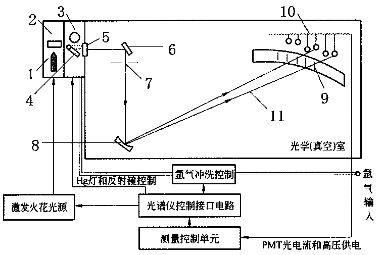
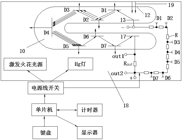
[0019] Such as image 3 As shown, a vacuum photoelectric direct-reading spectrometer includes a vacuum photoelectric direct-reading spectrometer body 18. It should be noted that, for the simplicity of the picture, image 3 The entire structure of the vacuum photoelectric direct reading spectrometer body 18 is not shown, and the vacuum photoelectric direct reading spectrometer body 18 is in the image 3 In , only a rectangular box is used to illustrate, and only the improved related structure is shown. For the specific structure, please refer to figure 1 As shown, the combustion chamber in the upper left corner is included, and the electrode 1 and...


PUM


Abstract

The invention discloses a vacuum photoelectric direct-reading spectrometer which comprises a vacuum photoelectric direct-reading spectrometer body, wherein the vacuum photoelectric direct-reading spectrometer body comprises an excitation spark light source for controlling an electrode excitation sample to emit a characteristic spectrum, a Hg lamp capable of generating a base body line, and a photomultiplier for converting a spectrum line strength into a current signal and amplifying a current. The vacuum photoelectric direct-reading spectrometer is characterized by further comprising a singlechip, a keyboard, a timer, a display and a power line switch, wherein the keyboard, the timer, the display and the power line switch are respectively connected with the singlechip, and the power line switch is connected with the excitation spark light source, the Hg lamp and the photomultiplier respectively. According to the vacuum photoelectric direct-reading spectrometer, the working time of the vacuum photoelectric direct-reading spectrometer can be set as required, and the situations that the service life is reduced and energy source is wasted due to long-term working are prevented. Furthermore, a housing of the photomultiplier is prevented from being overlong, so that the vacuum photoelectric direct-reading spectrometer is unlikely to be damaged.

Description

technical field [0001] The invention relates to a vacuum photoelectric direct reading spectrometer. Background technique [0002] The photoelectric direct reading spectrometer is a rapid quantitative analysis instrument for analyzing the components of ferrous and non-ferrous metals. It has many advantages such as fast analysis speed and high accuracy (relative error is about 1%), and is suitable for a wide wavelength range. Its photomultiplier tube has a strong ability to amplify signals, and different magnifications can be used for different strong and weak spectral lines. The phase difference can reach 10,000 times, and the linear range is wide, which can be used for high content analysis, such as Al, Pb, Mg, Zn, Sn, Fe, Co, Ni, Ti, Cu and other matrix analysis. It is widely used in metallurgy, machinery and other industrial sectors. It is one of the effective means to control product quality for on-line analysis before smelting furnace and product inspection in central l...

Claims


Application Information

Patent Timeline
Patent Type & Authority Applications(China)
IPC IPC(8): G01N21/67G01N21/01
Inventor 李泉岳所祥杨志强杭文辉
Owner JIANGSU XINZHIYUAN INSTR
Learn More