
Ceramic ball valve high in corrosion resistance and erosive abrasion resistance

A ceramic ball valve and corrosion-resistant technology, applied in the field of ceramic ball valves, can solve the problems of valve wear, leakage and scratches in the multi-phase flow conveying system, achieve good comprehensive performance, wide application prospects, and ensure the effect of sealing

Inactive Publication Date: 2014-08-06
ZHEJIANG SCI-TECH UNIV
View PDF6 Cites 3 Cited by
  • Summary
  • Abstract
  • Description
  • Claims
  • Application Information

AI Technical Summary

Problems solved by technology

Since a one-million-ton coal direct liquefaction demonstration project was put into operation at the end of 2008, unplanned downtime accidents caused by flow wear are very common, especially the valve wear and leakage of the multiphase flow conveying system, which seriously restricted the entire demonstration project The long-term operation of the coal chemical industry has a high risk of production safety, and the benefits of scale intensification of coal chemical industry are not significant
At present, high-temperature and high-pressure metal-sealed wear-resistant ball valves are mostly used in the core equipment of the coal chemical industry. However, metal-sealed ball valves are often scoured by high-temperature multi-phase flow under harsh conditions, showing that the seat and the spherical surface are not tightly sealed and have scratches. Partial shedding of spherical alloy, low hardness, etc.

Method used


Image

  • Ceramic ball valve high in corrosion resistance and erosive abrasion resistance
  • Ceramic ball valve high in corrosion resistance and erosive abrasion resistance

Examples


Embodiment Construction

[0014] The present invention will be further described below in conjunction with drawings and embodiments.

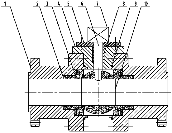
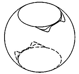
[0015] Such as figure 1 , figure 2 As shown, the present invention includes two valve bodies 1, valve seat 2, rebound gasket 3, valve cover 4, packing gland 5, valve stem 6, actuator 7, graphite packing 8, O-ring 9 with the same structure and the bow-shaped notch valve ball 10; the two valve bodies 1 and the valve cover 4 are connected and fixed by bolts, and are sealed by O-rings 9; the inner centers of the two valve bodies 1 are respectively equipped with detachable stepped valve seats 2, and the stepped The outer shoulder of the shaped valve seat 2 and the inner side of the valve body 1 are fixed by the rebound gasket 3, and the inner side of the valve seat 2 forms a surface contact seal with the bow-shaped notch valve ball 10; the valve stem 6 is embedded in the circumferential gap connecting the valve cover 4 Graphite filler 8, and fixed by bolts through the pac...


PUM


Abstract

The invention discloses a ceramic ball valve high in corrosion resistance and erosive abrasion resistance. Two valve bodies are in linkage with a valve cover, and the two valve bodies and the valve cover are sealed through an O-type gasket. Stepped valve seats are installed in the centers of the inner sides of the two valve bodies respectively. Shoulders of the stepped valve seats and the inner sides of the valve bodies are fixedly matched through resilience gaskets. The inner sides of the valve seats and an arch gap valve ball form a surface contact seal. Graphite packing is embedded into the circumferential gap of the connection between a valve rod and the valve cover and fixedly pressed through bolts by a packing gland. One end of the valve rod is inserted into the arch gap valve ball to be positioned, the other end of the valve rod is connected with an execution mechanism, the execution mechanism drives the arch gap valve ball to rotate through the valve rod, and the arch gap valve ball is a valve ball of a nonsymmetrical structure. The ceramic ball valve can be applied to multi-phase flow abrasion working conditions of coal chemical industries, petrochemical industries and electric power systems and is excellent in high temperature resistance and abrasion resistance, long in service life, good in comprehensive performance, capable of meeting the using requirements in the multi-phase flow harsh erosive abrasion environment and broad in application prospect.

Description

technical field [0001] The invention relates to a ceramic ball valve, in particular to a ceramic ball valve with high corrosion resistance and erosion wear applied to process industries such as coal chemical industry, petrochemical industry and power station system. Background technique [0002] Multiphase flow transportation is widely used in process industries such as petroleum, chemical industry, biology, pharmaceuticals, and metallurgy, and plays a very important role in the development of the national economy. Compared with other valves, ball valves have comprehensive advantages because of their small flow resistance, unrestricted flow direction, and rapid opening and closing. [0003] In recent years, in order to meet the needs of energy development, it is imperative to increase the national energy strategic reserves and vigorously develop coal chemical related industries. Since a one-million-ton coal direct liquefaction demonstration project was put into operation at...

Claims


Application Information

Patent Timeline
Patent Type & Authority Applications(China)
IPC IPC(8): F16K5/06F16K5/08
CPCF16K5/0663F16K5/0605F16K5/08F16K27/067
Inventor 偶国富肖定浩金浩哲
Owner ZHEJIANG SCI-TECH UNIV
Learn More