Eureka AIR delivers breakthrough ideas for toughest innovation challenges, trusted by R&D personnel around the world.

Flue gas denitration catalyst

A denitrification catalyst and catalyst technology, applied in the direction of physical/chemical process catalysts, metal/metal oxide/metal hydroxide catalysts, chemical instruments and methods, etc., can solve the problem of large smoke resistance, wear resistance, and poor reproducibility , poor operating performance of the unit, etc., to achieve good regeneration effect, long service life and improved safety

Inactive Publication Date: 2014-08-06
上海达源环境科技工程有限公司
View PDF7 Cites 21 Cited by
  • Summary
  • Abstract
  • Description
  • Claims
  • Application Information

AI Technical Summary

Problems solved by technology

[0005] The purpose of the present invention is to provide an improved flue gas denitrification catalyst, which can overcome some shortcomings of the prior art, such as relatively large resistance to flue gas, poor wear resistance, poor reproducibility, and poor operating performance of the unit.

Method used


Image

  • Flue gas denitration catalyst
  • Flue gas denitration catalyst
  • Flue gas denitration catalyst

Examples


Embodiment 1

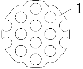
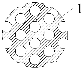
[0023] The flue gas denitrification catalyst uses 80% titanium dioxide as the carrier, 10% vanadium pentoxide as the main active ingredient, and additionally adds 10% WO (tungsten oxide) or 10% MoO 3 (Molybdenum trioxide) etc. are extruded into balls as catalyst auxiliary components, dried and sintered. Such as figure 2 As shown, the appearance of the catalytic material is as figure 2 As shown, the whole is spherical. The holes are evenly arranged inside the ball, the holes are cylindrical, the diameter is 15-60mm, the hole diameter is 5-12mm, the spacing can be adjusted according to the working conditions, and the specific surface area is about 300-600 m 2 / m 3 .

Embodiment 2

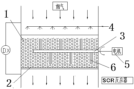
[0025] The flue gas denitrification catalyst uses 60% titanium dioxide as the carrier, 30% vanadium pentoxide as the main active ingredient, and additionally adds 10% WO (tungsten oxide) or 10% MoO 3 (Molybdenum trioxide) is extruded into a spherical shape as a catalyst auxiliary component, dried and sintered. The flue gas denitrification catalyst of the present invention is arranged in the tank that stirrer is arranged, as figure 1 shown. The flue gas passes through the tank from top to bottom, and the flue gas fully contacts and reacts with the catalyst material in the tank. When the pressure difference in and out of the notch reaches a certain value, the motor will start the stirring device to drive the catalytic material to stir, and at the same time perform steam purge to remove the ash attached to the surface of the catalyst pellets. The number of layers and height of the catalyst can be flexibly selected according to the specific denitration process.

[0026] When th...


PUM

PropertyMeasurementUnit
Diameteraaaaaaaaaa
Diameteraaaaaaaaaa
Apertureaaaaaaaaaa

Abstract

The invention relates to a flue gas denitration catalyst. The catalyst is characterized in that the catalyst comprises 60-90wt% of TiO2 (titanium dioxide), 10-30wt% of an activator and 1-10wt% of an auxiliary agent, the sum of the weight percentages of the above components is 100%, and the activator is one of V2O5 (vanadium pentoxide), V2O5-WO3 (vanadium pentoxide-tungsten trioxide) and or V2O5-MoO3 (vanadium pentoxide-molybdenum trioxide). The material composition and the processing process of the flue gas denitration catalyst like the material composition and the processing process of a honeycomb catalyst, so the flue gas denitration catalyst has excellent performances of the honeycomb catalyst, such as good catalysis effect, larger specific surface area, wear resistance, long service life and good regeneration effect. The flue gas denitration catalyst is much smaller than the honeycomb catalyst monomer, so the flue gas denitration catalyst has the advantages in transportation, installation, maintenance and regeneration. The flue gas denitration catalyst can cooperate with a specific groove to in order to make the running safety of a set using the flue gas denitration catalyst higher than the running safety of a set using the honeycomb catalyst.

Description

technical field [0001] The invention relates to the technical field of nitrogen oxide reduction catalytic materials, in particular to a flue gas denitrification catalyst, in particular to a catalytic material structure for flue gas denitrification of coal-fired boilers in thermal power plants. Background technique [0002] With the rapid development of my country's economy, the rapid increase in power demand has led to the continuous expansion of coal-fired boilers, and the extensive use of coal has led to more nitrogen oxides (ie NO X ) generation. During the "Twelfth Five-Year Plan" period, the emission of nitrogen oxides from thermal power plants will increase from 10.5 million tons in 2010 to 12 million tons. These nitrogen oxides will cause serious harm to China's atmospheric environment. It is urgent to control the emission of nitrogen oxides. Power plant denitrification has become the focus of work during the "Twelfth Five-Year Plan" period. [0003] Flue gas denitr...

Claims


Application Information

Patent Timeline
IPC IPC(8): B01J23/30B01D53/86B01D53/56
Inventor 吴勇魏艳平李春泉李锦杨葆华翟佳
Owner 上海达源环境科技工程有限公司
Why Eureka
Eureka Blog
Learn More