
LED crystal covering structure coated with fluorescent powder and manufacturing method of LED crystal covering structure coated with fluorescent powder

A phosphor powder and LED chip technology, applied in electrical components, electrical solid devices, circuits, etc., can solve the problems of product life cycle, luminous efficiency impact, electrode wire heat dissipation volume is limited, heat dissipation effect is not obvious, etc., to achieve rapid light decay , Simplified packaging process and small internal resistance

Inactive Publication Date: 2014-07-30
SHENZHEN SIMIN SCI & TECH
View PDF4 Cites 5 Cited by
  • Summary
  • Abstract
  • Description
  • Claims
  • Application Information

AI Technical Summary

Problems solved by technology

However, due to the limited heat dissipation volume of the electrode wire, the heat dissipation effect is not obvious, and its heat accumulation still has a major impact on the product life cycle and luminous efficiency
On the other hand, due to the welding process, the current LED technology is not suitable for the production of some smaller LED flip-chip structures, and the production process is costly and inefficient.

Method used


Image

  • LED crystal covering structure coated with fluorescent powder and manufacturing method of LED crystal covering structure coated with fluorescent powder
  • LED crystal covering structure coated with fluorescent powder and manufacturing method of LED crystal covering structure coated with fluorescent powder
  • LED crystal covering structure coated with fluorescent powder and manufacturing method of LED crystal covering structure coated with fluorescent powder

Examples


Embodiment Construction

[0023] The present invention will be further explained below in conjunction with accompanying drawing:

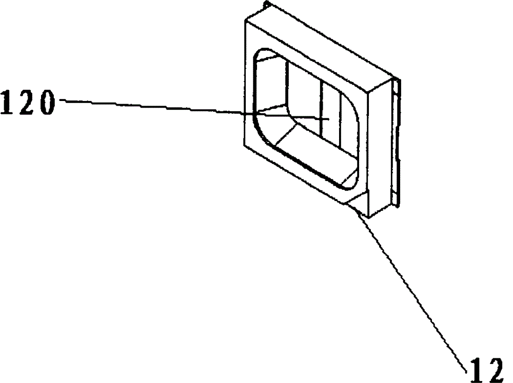
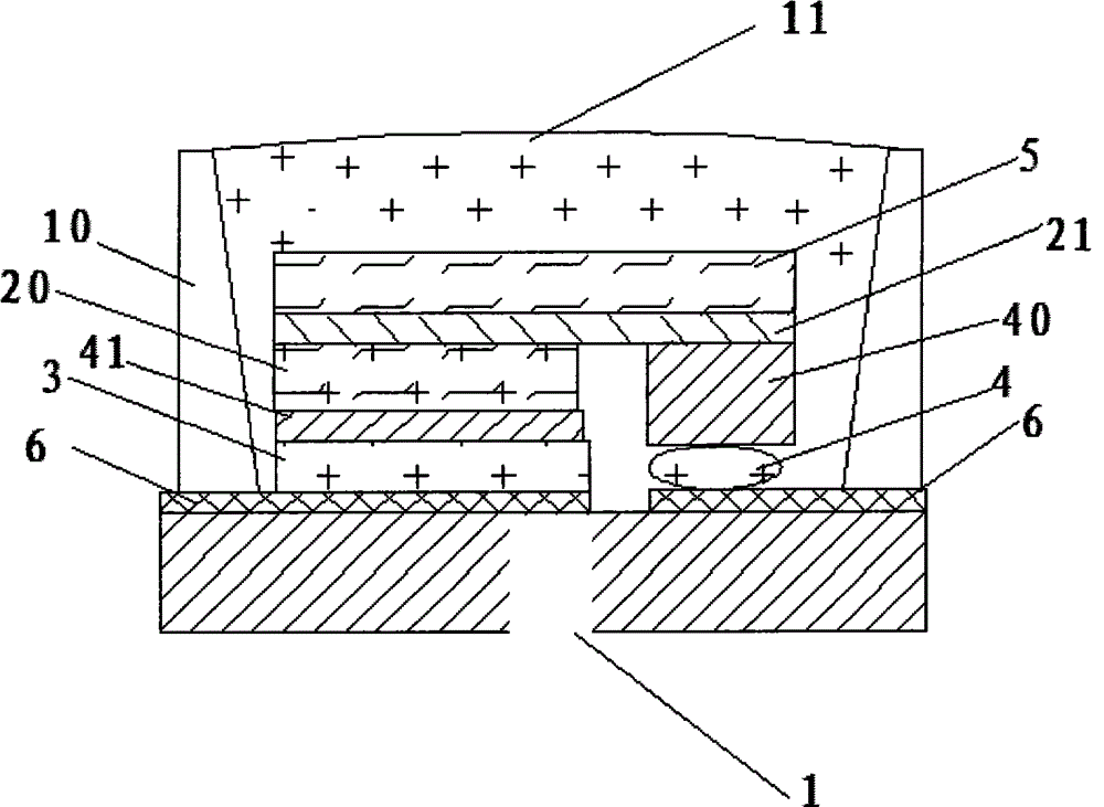
[0024] Such as figure 1 As shown, the present invention provides a LED flip-chip structure coated with phosphor powder, which includes a housing 10, a metal support 12, a substrate 1, an LED chip 2, a first electrode 3, a second electrode 4, a reflective layer 6 and The cover layer 5, the housing 10 is filled with fluorescent powder and silica gel 11, the upper end of the fluorescent powder 11 forms an arc-shaped surface, the reflective layer 6 is integrally formed on the substrate 1, and the LED chip includes a positive electrode 20 and a negative electrode 21. The electrode 20 is connected to the first electrode 3 , the negative electrode 21 is connected to the second electrode 4 , and the covering layer 5 is arranged on the top of the LED chip 2 . In this embodiment, the covering layer 5 is sapphire or other crystals. The material of the first electrode 3 and the secon...


PUM


Abstract

The invention provides an LED crystal covering structure coated with fluorescent powder. The LED crystal covering structure comprises a shell, a substrate, an LED chip, a first electrode, a second electrode, a reflecting layer and a covering layer. The reflecting layer is integrally formed on the substrate, the LED chip is welded to the substrate in an inversed mode and provided with a positive electrode and a negative electrode, the positive electrode is connected with the first electrode, the negative electrode is connected with the second electrode, and the covering layer covers the upper portion of the LED chip. The LED crystal covering structure has the advantages that the electric conduction area is large, internal resistance is small, a large current can pass through the LED crystal covering structure, and excessively-large heat caused by the large internal resistance can be reduced; the light emitting efficiency is high, and the light emitting angle is large. A packaging technology is simplified, the packaging cost is reduced, and the production efficiency is improved; light attenuation is low, rapid light attenuation caused by the heat is avoided, the service life of the LED chip is accordingly prolonged, and the service life of the LED crystal covering structure is more than ten times that of a common lamp.

Description

technical field [0001] The invention relates to a semiconductor structure, in particular to an LED flip-chip structure coated with fluorescent powder and a manufacturing method thereof. Background technique [0002] The LED industry is one of the industries that has attracted the most attention in recent years. Up to now, LED products have the advantages of energy saving, power saving, high efficiency, fast response time, long life cycle, mercury-free, and environmental protection benefits. However, Usually, most of the input power of LED high-power products will be converted into heat energy. Generally speaking, if the heat energy generated by LED light cannot be exported, the junction temperature of LED will be too high, which will affect the product life cycle, luminous efficiency and stability. Wait. At present, the heat dissipation method of the flip-chip LED packaging structure is mainly conducted through the LED electrode wires to the system circuit board. However, ...

Claims


Application Information

Patent Timeline
Patent Type & Authority Applications(China)
IPC IPC(8): H01L33/48H01L33/62
CPCH01L2224/14H01L2224/16245H01L33/505H01L33/62H01L33/647H01L2933/0025H01L2933/0066H01L2933/0075
Inventor 吕吉隆杨秋湖
Owner SHENZHEN SIMIN SCI & TECH
Learn More